Engine Maintenance
Engine MaintenanceValve Clearance Adjustment
Valve Clearance Adjustment
VALVE CLEARANCE ADJUSTMENT

1 Valve lifter 2 Pad 3 Retainer 4 Spring seat
Valve Clearance (Cold):
Intake: 0.11 -0.20 mm (0.004- 0.008 in)
Exhaust: 0.21- 0.30 mm (0.008- 0.012 in)
Measurement
1. Remove:
• Seat
• Fuel tank
• Horns
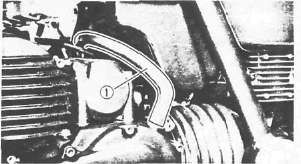
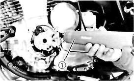
• Ignition coil mount bolts (1)
2. Disconnect the spark plug caps

3. Remove:
• Ignition coils
• Spark plugs
• Cylinder head cover
• Left crankcase cover
4. Measure the valve clearance
NOTE:.
Be sure piston is at Top Dead Center (TDC) on compression stroke when measuring clearance.
Valve clearance measurement steps:
•Turn the crankshaft counterclockwise with a 19 mm (0.75 in) spanner.
NOTE:
Valve clearance must be measured when the engine is cool to the touch.

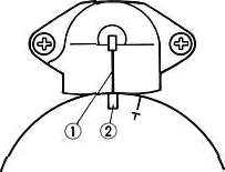
(1) Pickup coil mark
(2) TDC for No. 1 cylinder
(3) Firing range for the No. 1 cylinder
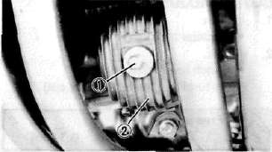
•Align the "T" mark (2) on the timing plate with the pickup coil mark (1) . When the "T" mark is aligned with the stationary pointer (2) . the piston is at top dead center (TDC).

• Measure the valve clearance using a Feeler Gauge (3).
• Record the measured amount if the clearance is incorrect.
Intake Valve (cold): 0.11- 0.20 mm (0.004- 0.008in)
Exhaust Valve (cold): 0.21- 0.30 mm (0.008- 0.012 in)
Measure valve clearance, in sequence, for Nos. 2, 4, and No. 3 cylinders.
Out of specification - Adjust clearance.
Firing Sequence: 1 -2-4-3

[A] Crankshaft counterclockwise turning angle. [Bl Cylinder [C] Combustion

Adjustment
1. Remove carburetors Refer to CHAPTER 3 "ENGINE REMOVAL".

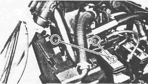
2. Loosen the cam chain tensioner end plug (1)
3. Remove the cam chain tensioner (2)

4. Remove:
•Cam chain guide (Upper) (1)
•Cam cap I3 (2)
•Cam cap E3 (3)
• Dowel pins
5. Remove:
•Cam chain sprocket bolts
•Cam caps
•Dowel pins

•Cam shafts (1)
•Cam chain sprockets (2)
NOTE:
Fasten safety wire to the cam chain to prevent it from falling into the crankcase.

6. Remove:
• Valve lifter (1)
• Pad (2)

Note the installed pad number (3). Round off the value as required:
|
Pad range |
Pad Availability: 25 increments |
|
|
No. 120 ~ No. 240 |
1.20 mm (0.047 in) 2.40 mm (0.094 in) |
Pads stepped in 0.05 mm (0.002 in) increments |
|
Note: Thickness of each pad is marked on the pad side wall. |
||
|
• Round off the hundredths digit of the installed pad number to the nearest 0.05 mm increment. |
||
|
Hundredths digit |
Rounded valve |
|
|
0 or 2 |
0 |
|
|
5 |
(NOT ROUNDED OFF) |
|
|
8 |
10 |
|
7. Select the proper pad from the appropriate chart (next 2 pages, links below)
EXAMPLE:
Installed pad number = 175 (1.75 mm)
Rounded off digit = 175
NOTE:
Pads can only be selected in 0.05 mm (0.02 in) increments.
* Locate the "Rounded off Pad Number" on the chart, and then find the measured valve clearance. The point where these coordinates intersect is the new pad number.
NOTE:
Use the new pad number as a guide only as the number must be verified.

8. Install:
• Pad (1)
• Valve lifter (2)
• Cam shaft
• Cam chain sprocket
Refer to CHAPTER 3 "ENGINE ASSEMBLY"

9. Recheck the valve clearance.
If the clearance is incorrect, repeat all of the clearance adjustment steps until the proper clearance is obtained.
Assembly
1. Reverse removal steps.
Inspect the head cover gasket and replace it if damaged.
2. Tighten:
• Cylinder head cover bolts
• Fuel tank bolts
Head Cover Bolt: 10 Nm (1.0 m.kg, 7.2 ft-lb)
Fuel Tank Bolt: 10 Nm (1.0 m.kg, 7.2 ft-lb)
Exhaust Valve Shim Chart
Exhaust Valve Shim ChartEXHAUST
|
MEASURED CLEARANCE |
INSTALLED PAD NUMBER |
|||||||||||||||||||||||||
|
120 |
125 |
130 |
135 |
140 |
145 |
150 |
155 |
160 |
165 |
170 |
175 |
180 |
185 |
190 |
195 |
200 |
205 |
210 |
215 |
220 |
225 |
230 |
235 |
240 |
||
|
0.00-0.02 |
|
|
|
|
|
120 |
125 |
130 |
135 |
140 |
145 |
150 |
155 |
160 |
165 |
170 |
175 |
180 |
185 |
190 |
195 |
200 |
205 |
210 |
215 |
|
|
0.03-0.07 |
|
|
|
|
120 |
125 |
130 |
135 |
140 |
145 |
150 |
155 |
160 |
165 |
170 |
175 |
180 |
185 |
190 |
195 |
200 |
205 |
210 |
215 |
220 |
|
|
0.08-0.12 |
|
|
|
120 |
125 |
130 |
135 |
140 |
145 |
150 |
155 |
160 |
165 |
170 |
175 |
180 |
185 |
190 |
195 |
200 |
205 |
210 |
215 |
220 |
225 |
|
|
0.13-0.17 |
|
|
120 |
125 |
130 |
135 |
140 |
145 |
150 |
155 |
160 |
165 |
170 |
175 |
180 |
185 |
190 |
195 |
200 |
205 |
210 |
215 |
220 |
225 |
230 |
|
|
0.18-0.20 |
|
120 |
125 |
130 |
135 |
140 |
145 |
150 |
155 |
160 |
165 |
170 |
175 |
180 |
185 |
190 |
195 |
200 |
205 |
210 |
215 |
220 |
225 |
230 |
235 |
|
|
0.21-0.30 |
RECOMMENDED CLEARANCE |
|||||||||||||||||||||||||
|
0.31-0.32 |
125 |
130 |
135 |
140 |
145 |
150 |
155 |
160 |
165 |
170 |
175 |
180 |
185 |
190 |
195 |
200 |
205 |
210 |
215 |
220 |
225 |
230 |
235 |
240 |
|
|
|
0.33-0.37 |
130 |
135 |
140 |
145 |
150 |
155 |
160 |
165 |
170 |
175 |
180 |
185 |
190 |
195 |
200 |
205 |
210 |
215 |
220 |
725 |
230 |
735 |
240 |
|
||
|
0.38-0.42 |
135 |
140 |
145 |
150 |
155 |
160 |
165 |
170 |
175 |
180 |
185 |
190 |
195 |
200 |
205 |
210 |
215 |
220 |
225 |
230 |
235 |
240 |
|
|||
|
0.43-0.47 |
140 |
145 |
150 |
155 |
160 |
165 |
170 |
175 |
180 |
185 |
190 |
195 |
200 |
205 |
210 |
215 |
220 |
225 |
230 |
235 |
240 |
|
||||
|
0.48-0.52 |
145 |
150 |
155 |
160 |
165 |
170 |
175 |
180 |
185 |
190 |
195 |
200 |
205 |
210 |
215 |
220 |
225 |
230 |
235 |
240 |
|
|||||
|
0.53-0.57 |
150 |
155 |
160 |
165 |
170 |
175 |
180 |
185 |
190 |
195 |
200 |
205 |
210 |
215 |
220 |
225 |
730 |
235 |
740 |
|
||||||
|
0.58-0.62 |
155 |
160 |
165 |
170 |
175 |
180 |
185 |
190 |
195 |
200 |
205 |
210 |
215 |
220 |
225 |
230 |
235 |
240 |
|
|||||||
|
0.63-0.67 |
160 |
165 |
170 |
175 |
180 |
185 |
190 |
195 |
200 |
205 |
210 |
215 |
220 |
225 |
230 |
235 |
240 |
|
||||||||
|
0.68-0.72 |
165 |
170 |
175 |
180 |
185 |
190 |
195 |
200 |
205 |
210 |
215 |
220 |
225 |
230 |
235 |
240 |
|
|||||||||
|
0.73-0.77 |
170 |
175 |
180 |
185 |
190 |
195 |
200 |
205 |
210 |
215 |
220 |
225 |
230 |
235 |
240 |
|
||||||||||
|
0.78-0.82 |
175 |
180 |
185 |
190 |
195 |
200 |
205 |
210 |
215 |
220 |
225 |
230 |
235 |
240 |
|
|||||||||||
|
0.83-0.87 |
180 |
185 |
190 |
195 |
200 |
205 |
210 |
215 |
220 |
225 |
230 |
235 |
240 |
|
||||||||||||
|
0.88-0.92 |
185 |
190 |
195 |
200 |
205 |
210 |
215 |
220 |
225 |
230 |
235 |
240 |
|
|||||||||||||
|
0.93-0.97 |
190 |
195 |
200 |
205 |
210 |
215 |
220 |
225 |
230 |
235 |
240 |
|
||||||||||||||
|
0.98-1.02 |
195 |
200 |
205 |
210 |
215 |
220 |
225 |
230 |
235 |
240 |
VALVE CLEARANCE (cold): 0.21 - 0.30 mm (0.008 - 0.012 in) Example: Installed is 175 Measured clearance is 0.35 mm (0.014 in) Replace 175 pad with 185 pad |
|||||||||||||||
|
1.03-1.07 |
200 |
205 |
210 |
215 |
220 |
225 |
230 |
235 |
240 |
|
||||||||||||||||
|
1.08-1.12 |
205 |
210 |
215 |
220 |
225 |
230 |
235 |
240 |
|
|||||||||||||||||
|
1.13-1.17 |
210 |
215 |
220 |
225 |
230 |
235 |
240 |
|
||||||||||||||||||
|
1.18-1.22 |
215 |
220 |
225 |
230 |
235 |
240 |
|
|||||||||||||||||||
|
1.23-1.27 |
220 | 225 |
230 |
235 |
240 |
|
||||||||||||||||||||
|
1.28-1.32 |
225 |
230 |
235 |
240 |
|
|||||||||||||||||||||
|
1.33-1.37 |
230 |
235 |
240 |
|
||||||||||||||||||||||
|
1.38-1.42 |
235 |
240 |
|
|||||||||||||||||||||||
| 1.43-1.47 | 240 | |||||||||||||||||||||||||
Intake Valve Shim Chart
Intake Valve Shim ChartINTAKE
|
MEASURED CLEARANCE |
INSTALLED PAD NUMBER |
120 |
125 |
130 |
135 |
140 |
145 |
150 |
155 |
160 |
165 |
170 |
176 |
180 |
185 |
190 |
195 |
200 |
205 |
210 |
215 |
220 |
225 |
230 |
235 |
240 |
0.00-0.02 |
|
|
|
120 |
125 |
130 |
135 |
140 |
145 |
150 |
155 |
160 |
165 |
170 |
175 |
180 |
185 |
190 |
195 |
200 |
205 |
210 |
215 |
220 |
225 |
0.03-0.07 |
|
|
120 |
125 |
130 |
135 |
140 |
145 |
150 |
155 |
160 |
165 |
170 |
175 |
180 |
185 |
190 |
195 |
200 |
205 |
210 |
215 |
220 |
225 |
230 |
0.08-0.10 |
|
120 |
125 |
130 |
135 |
140 |
145 |
150 |
155 |
160 |
165 |
170 |
175 |
l80 |
185 |
190 |
195 |
200 |
205 |
210 |
215 |
220 |
225 |
230 |
235 |
0.11-0.20 |
RECOMMENDED CLEARANCE |
0.21-0.22 |
125 |
130 |
135 |
140 |
145 |
150 |
155 |
160 |
166 |
170 |
175 |
180 |
185 |
190 |
19b |
200 |
205 |
210 |
215 |
220 |
225 |
230 |
235 |
240 |
|
0.23-0.27 |
130 |
135 |
140 |
145 |
150 |
155 |
160 |
165 |
170 |
175 |
180 |
185 |
190 |
195 |
200 |
205 |
210 |
215 |
220 |
225 |
230 |
235 |
240 |
|
0.28-0.32 |
135 |
140 |
145 |
150 |
155 |
160 |
165 |
170 |
175 |
180 |
185 |
190 |
195 |
200 |
205 |
210 |
215 |
220 |
225 |
230 |
235 |
240 |
|
0.33-0.37 |
140 |
145 |
150 |
155 |
160 |
165 |
170 |
175 |
180 |
185 |
190 |
195 |
200 |
205 |
210 |
215 |
220 |
225 |
230 |
235 |
240 |
|
0.38-0.42 |
145 |
150 |
155 |
160 |
165 |
170 |
175 |
180 |
185 |
190 |
195 |
200 |
205 |
210 |
215 |
220 |
225 |
230 |
235 |
240 |
|
0.43-0.47 |
150| |
155 |
160 |
165 |
170 |
175 |
180 |
185 |
190 |
195 |
200 |
205 |
210 |
215 |
220 |
225 |
230 |
235 |
240 |
|
0.48-0.52 |
155 |
160 |
165 |
170 |
175 |
180 |
185 |
190 |
195 |
200 |
205 |
210 |
215 |
220 |
225 |
230 |
235 |
240 |
|
0.53-0.57 |
160 |
165 |
170 |
175 |
180 |
18b |
190 |
195 |
200 |
205 |
210 |
215 |
220 |
225 |
230 |
235 |
240 |
|
0-58-0.62 |
165 |
170 |
175 |
180 |
185 |
190 |
195 |
200 |
205 |
210 |
215 |
220 |
225 |
230 |
235 |
210 |
|
0.63-0.67 |
170 |
175 |
180 |
185 |
190 |
195 |
200 |
205 |
210 |
215 |
220 |
225 |
230 |
235 |
240 |
|
0.68-0.72 |
175 |
180 |
185 |
190 |
195 |
200 |
205 |
210 |
215 |
220 |
225 |
230 |
235 |
240 |
|
|
0.73-0.77 |
180 |
185 |
190 |
195 |
200 |
205 |
210 |
215 |
220 |
225 |
230 |
235 |
240 |
|
0.78-0.82 |
185 |
190 |
195 |
200 |
205 |
210 |
215 |
220 |
225 |
230 |
235 |
240 |
|
0.83-0.87 |
190 |
195 |
200 |
205 |
210 |
215 |
220 |
225 |
230 |
235 |
240 |
|
0.88-0.92 |
195 |
200 |
205 |
210 |
215 |
220 |
225 |
230 |
235 |
240 |
|
0.93-0.97 |
200 |
205 |
210 |
215 |
220 |
225 |
230 |
235 |
240 |
|
0.98-1.02 |
205 |
210 |
215 |
220 |
225 |
230 |
235 |
240 |
VALVE CLEARANCE (cold): 0.11 -0.20 mm (0.004 - 0.008 in) Example: Installed is 175 Measured clearance is 0.24 mm (0.009 in) Replace 175 pad with 185 pad |
1.03-1.07 |
210 |
215 |
220 |
225 |
230 |
235 |
240 |
|
1.08-1.12 |
215 |
220 |
225 |
230 |
235 |
240 |
|
1.13-1.17 |
220 |
225 |
230 |
235 |
240 |
|
1.18-1.22 |
225 |
230 |
235 |
240 |
|
1.23-1.27 |
230 |
235 |
240 |
|
1.28-1.32 |
235 |
240 |
|
1.33-1.37 |
240 |
|
|
Spark Plug, Crankcase Ventilation, Fuel Line and Exhaust
Spark Plug, Crankcase Ventilation, Fuel Line and ExhaustSPARK PLUG
1. Remove spark plugs

2. Inspect:
• Electrode (1) for wear/damage.
• Insulator color (2)
3. Measure the plug gap (3) using a Wire Gauge or Feeler Gauge. Regap as reqired.
Plug Gap: 0.6 - 0.7 mm (0.024 - 0.028 in)
Clean the plug with a spark plug cleaner if necessary.
Standard Spark Plug: DR8ES-L (NGK) X24ESR-U (NIPPONDENSO)
Before installing a spark plug, clean the gasket surface and plug surface.
4. Tighten Spark plug(s) to 17.5 Nm (1.75 m-kg, 12.5 ft-lb)
NOTE:
Finger-tighten the spark plug(s) before torquing to specification.
CRANKCASE VENTILATION SYSTEM
1. Inspect the crankcase ventilation hose (1). Replace damaged hoses.

FUEL LINE
1. Inspect:
• Fuel hose (1)
• Vacuum hose (2)
Replace damaged hoses.

INTAKE MANIFOLD
1. Tighten:
• Carburetor clamps
• Carburetor joint bolts
2. Inspect:
• Carburetor joint
• Gaskets
Replace if necessary.

EXHAUST SYSTEM
1. Inspect:
•Exhaust pipe gasket(s) (1)
• Muffler clamp gasket(s) (2)
Damage > Replace.
Exhaust gas leakage > Repair.
2. Tighten:
• Exhaust pipe bolts
• Muffler bolts
Exhaust Pipe Flange (3) :10 Nm(1.0m-kg, 7.2ft-b)
Exhaust Pipe Clamp (4) :20 Nm (2.0 m-kg, 14 ft-lb)
Exhaust Chamber Mount (5): 25 Nm (2.5 m-kg, 18 ft-lb)
Muffler Clamp (6): 20 Nm (2.0 m-kg, 14 ft-lb)
Muffler Bracket (7) 20 Nm (2.0 m-kg, 14 ft-lb)
Carburettor - Idle speed and Synchronization
Carburettor - Idle speed and SynchronizationIDLE SPEED

1. Adjust the idle speed. Warm up the engine and turn the throttle stop screw (1) to adjust.
Idle Speed:
1,050 ± 50 r/min
CARBURETOR SYNCHRONIZATION
Carburetor Adjustment
Carburetors must be set properly before synchronizing the carburetors.
NOTE:
Valve clearance must be set properly before synchronizing the carburetors.

1. Remove:
• Seat
• Fuel tank
2. Disconnect:
• Vacuum plugs (1)
• Vacuum hose (2)

3. Install:
• Vacuum Gauge (90890-03094)(1)
• Suitable test fuel tank
4. Start the engine and let it warm up.

5. Turn throttle stop screw (1) to adjust idle speed to 1,050 ± 50r/min.
6. Adjust carburetor synchronization

Carburetor synchronization adjustment steps:
•Synchronize the carburetor No. 1 to the carburetor No. 2 by turning the synchronizing screw "1" until the both gauge readings are the same.
•Rev. the engine for a fraction of a second, two or three times, and check the synchronization again.
Vacuum Pressure at Idle Speed: 24 kPa (180 mm Hg, 7.1 in Hg)
Vacuum Synchronous Difference: 0.7 kPa (5 mm Hg, 0.2 in Hg)
• Repeat the above steps to synchronize the carburetor No. 4 to the carburetor No.3 by turning the synchronizing screw " 3 " until the both gauge readings are the same.
• Repeat the same steps to synchronize No. 3 carburetor to No. 2 carburetor, then turn synchronizing screw " 2 " until both gauge readings are the same.
Engine Oil
Engine OilENGINE OIL

At 5°C(40°F) or Higher: Yamalube 4-Cycle Oil or SAE 20W40 Type SE Motor Oil
At15°C(60°F) or Lower: SAE 10W30 Type SE Motor Oil
Note:
recommended engine oil classification; API Service "SE", "SF" type or equivalent (e.g. "SF-SE", "SF-SE-CC", "SF-SE-SD" etc.)
Oil Level Measurement
1. Check the oil level. Add as required.
Oil level visual inspection steps:
•Place the motorcycle on its centerstand and warm up the engine for several minutes.
NOTE:
Position the motorcycle straight up when checking oil level, a slight tilt to the side can produce false readings.

• Stop the engine and visually check the oil level through the level window (1) .
(2) Maximum
(3) Minimum
Oil Change (Without filter)
1. Warm up the engine for several minutes, then place a receptacle under the engine.
2. Remove: The oil filler cap

3. Remove the drain plug (1) and drain the engine oil.
4. Replace and tighten the drain plug
Engine Drain Plug: 43 Nm (4.3 m-kg, 31 fMb)
5. Fill the crankcase with engine Oil: 2.5 L (2.2 Impqt, 2.6 US qt)
CAUTION:
Do not allow foreign material to enter the crank-case.
6. Install the filler cap
Oil Change (With filter)
1. Warm up the engine and place a receptacle under the engine.
2. Remove:
• Oil filler cap
• Drain plug
Drain the engine oil.
3. Remove:
• Oil filter bolt (1)
• Filter cover (2)
4. Replace and tighten the drain plug
Engine Drain Plug:
43 Nm (4.3 m-kg, 31 ftlb)
5. Install:

• Oil filter bolt 1
• Spring 2
• Washer 3
• Oil filter (New) 4
• O-ring 5 (x2, one on bolt, one on cover)
• Oil filter assembly

NOTE:
• Be sure the O-ring 5 is positioned properly.
• Fit the filter cover projection into the crank-case cover slot.
6. Tighten the oil filter bolt
Oil Filter Bolt: 15 Nm (1.5 nvkg. 11 ftlb)
7. Fill the crankcase with Engine Oil: 2.8 L (2.5 imp qt, 3.0 US qt)
8. Install the oil filler cap
9. Warm up the engine and check for oil leaks. Stop the engine instantly if leaking occurs.
10. Check the oil level
Level low — Add sufficient oil.
Coolant
CoolantCOOLANT

Recommended Coolant:
High Quality Ethylene Glycol Antifreeze Containing Anti-corrosion for Aluminum Engine Inhibitors Coolant and Water
Mixed Ratio: 50%/50%
Total amount: 2.4 L (2.11 Imp qt, 2.54 US qt)
Reservoir Tank Capacity: 0.49 L (0.43 Imp qt, 0.52 US qt)
From "LOW" to "FULL" Level: 0.14 L (0.12 Imp. qt, 0.15USqt)
WARNING:
Do not remove the radiator cap when the engine and radiator are hot. Scalding hot fluid and steam may be blown out under pressure, which could cause serious injury.
When the engine has cooled, open the radiator can by the following procedure: Place a thick rag, like a towel, over the radiator cap, slowly rotate the cap counterclockwise to the detent. This procedure allows any residual pressure to escape. When the hissing sound has stopped, press down on the cap while turning counterclockwise and remove it.
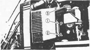
(1) "FULL" level (2) "LOW" level
Coolant Level Check
1. Check:
•Coolant level Coolant level low > Add sufficient coolant.

2. Remove:
• Reservoir tank cap (3)
• Cap retainer (4)
• Radiator cap (5)
3. Add:
• Coolant
Clutch Adjustment
Clutch Adjustment xjcdadmin Mon, 05/04/2009 - 16:25CLUTCH ADJUSTMENT

1. Loosen the adjuster locknut (1)
2. Adjust the clutch lever free play (a) by turning adjuster (2) in or out.
Free Play (a): 2 - 3mm (0.08-0.12 in)

3. If free play can not be adjusted, adjust by clutch cable length adjuster.
4. Loosen the adjuster locknuts (1)
5. Adjust clutch lever free play (a) by turning clutch cable length adjuster (2)
Ignition Timing Check
Ignition Timing CheckIGNITION TIMING CHECK
Flywheel is marked as follows:
(1) Pickup coil mark
(2) TDC for No. 1 cylinder
(3) Firing range for the No. 1 cylinder
1. Check:
• Ignition timing
Ignition timing check steps:
• Remove the cover.
• Connect the Timing Light (YU-08037) (1) to No. 1 cylinder spark plug lead.
• Warm up the engine and let it idle at the specified idle speed of 1.050 ± 50 r/min.
• Visually check the upper pickup coil mark (T) is within the firing range (2) indicated on timing plate.
Incorrect firing — Check timing plate and/or pickup assembly (tightness damage)
Refer to CHARTER 6. "ELECTRICAL" for further information.
(1) Pickup coil mark.
(2) Firing range for the No. 1 cylinder
Compression Pressure Measurement
Compression Pressure MeasurementNOTE:
Insufficient compression pressure will result in performance loss.
1. Measure:
•Valve clearance
Out of specification > Adjust.
2. Warm up the engine.
3. Remove:
•Spark plugs
4. Measure:
• Compression pressure

Compression pressure measurement steps:
• Install the Compression Gauge (90890-03081) (1) using an adapter.
• Crank over the engine with the electric starter (be sure the battery is fully charged) with the throttle wide-open until the compression reading on the gauge stabilizes.
• Check readings with specified levels (See chart).
Compression Pressure (at sea level):
Standard: 1,059 kPa (10.8 kg/cm2, 154 psi)
Minimum: 1,098 kPa (11.2 kg/cm2, 159 psi)
Maximum: 1,138 kPa (11.6 kg/cm2, 165 psi)
WARNING:
When cranking the engine, ground all of the spark plug leads to prevent sparking.
• Repeat the previous steps for the other cylinders.
• If pressure falls below the minimum level:
1) Squirt a few drops of oil into the affected cylinder.
2) Measure the compression again.
Compression Pressure (with oil introduced into cylinder)
|
Higher than without oil |
Worn or damaged pistons |
|
Same as without oil |
Defective ring(s), valves, cylinder head gasket or piston is possible. |
|
Above maximum level |
Inspect cylinder head, valve surfaces, or piston crown for carbon deposits. |
NOTE:
The different between the highest and lowest cylinder compression readings must not vary more than the specified value.
Difference between Each Cylinder: Less than 98 kPa (1 kg/cm2, 14 psi)