Chapter 3, ENGINE OVERHAUL
Chapter 3, ENGINE OVERHAULNOTE: It is not necessary to remove the engine in order to remove the following components:
• Piston
• Clutch
• Carburetor
• Oil pump
• Water pump
Engine Removal
Engine RemovalPREPARATION FOR REMOVAL

1. Remove all dirt, mud, dust, and foreign material before removal and disassembly.

2. Use proper tools and cleaning equipment. Refer to CHAPTER 1, "SPECIAL TOOLS."
NOTE:
When disassembling the engine, keep mated parts together. This includes gears, cylinders, pistons, and other parts that have been "mated" through normal wear. Mated parts must be reused as an assembly or replaced.

3. During the engine disassembly, clean all parts and place them in trays in the order of disassembly. This will speed up assembly time and help assure that all parts are correctly reinstalled in the engine.
SEAT AND FUEL TANK
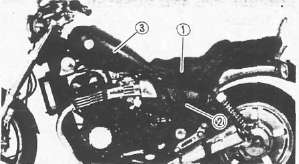
1. Remove:
• Seat 1
• Side cover 2
• Fuel tank 3
2. Drain the engine Oil
BATTERY
1. Disconnect the battery leads
NOTE:
Disconnect the negative lead first.
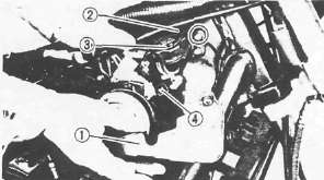
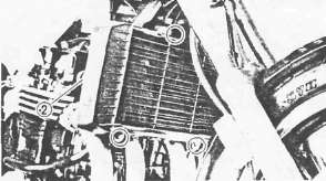
RADIATOR
1. Remove:
• Panel 1
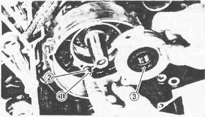
• Radiator cap cover 2
• Radiator cap 3
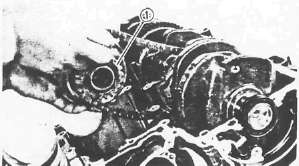
2. Disconnect the electric fan motor lead 4
3. Drain:
• Coolant (in the radiator)
• Coolant (in the radiator pipe)
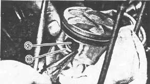
4. Disconnect:
• Radiator hose (Inlet) 1
• Radiator hose (Outlet) 2
5. Remove the radiator
CAUTION:
Do not bend or damage any of the radiator fins when removing the radiator from the motorcycle or when storing it.
EXHAUST PIPE AND MUFFLER
1. Remove the header nuts
2. Loosen the clamp bolts
3. Remove the exhaust header pipes 1
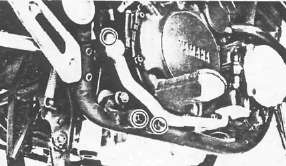
4. Remove:
• Chamber mount bolt 1
• Muffler mount bolts 2
• Mufflers with chamber
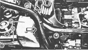
CARBURETOR AND CABLES
1. Remove:
• Air cleaner case 1 mount bolts.
• Side cover 2
2. Loosen the clamp screws
3. Push the air cleaner case toward the rear to disconnect air outlet hoses from carburetors.
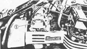
4. Disconnect:
• Choke cable 1
• Throttle cables 2
• Clutch cable 3
5. Remove the carburetors
NOTE:
After removing the carburetors, cover the carburetors with a clean cloth to keep dust and dirt out.
6. Disconnect:
• Radiator hoses 4
• Crankcase ventilation hose
CONNECTOR
1. Remove panel 1
2. Disconnect:
• Pickup coil lead
• Generator lead
• Neutral switch lead
• Oil level switch lead
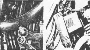
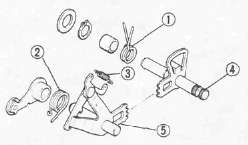
FOOTREST, BRAKE PEDAL, AND DRIVE SHAFT
1. Remove:
• Brake pedal
• Footrests (Left and Right)
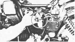
2. Disconnect:
• Starter motor lead 1 (from starter motor)
• Rubber boot
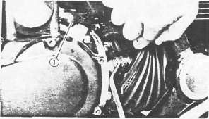
3. Remove the joint bolts
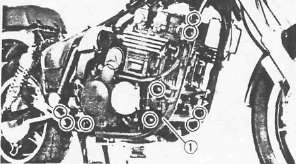
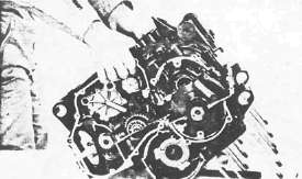
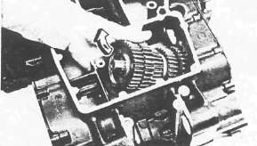
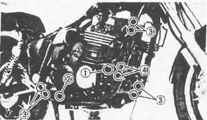
ENGINE REMOVAL
1. Place a suitable stand under the engine.
2. Remove:
• Downtube frame 1
• Mount bolts
3. Remove the engine assembly from chassis right side.
Caution:
The engine is heavy, awkward and a tight fit. An assistant may be required to avoid dropping it.
There are many pinch points between the various parts of the engine and sections of the frame. Take care to avoid injury.
NOTE: If it is necessary to remove the engine without assistance, it may be worthwhile to lay the bike on it's right side and lift the frame off the bike. Take care to avoid damage to such pieces as mirrors, levers and chrome.
Engine Disassembly
Engine DisassemblyCylinder Head Removal
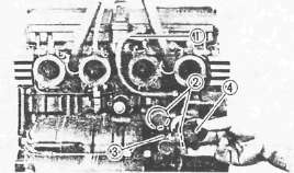
Cylinder Head RemovalRADIATOR PIPES, CARBURETOR JOINT, AND OIL DELIVERY PIPE
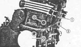
1. Remove:
• Radiator pipe 1
• Cover (Right) 2
2. Drain the coolant (in the cylinder) by removing drain bolts 3
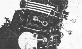
3. Remove;
• Water pump joint 1
• Radiator pipes 2
• Carburetor joints
• Bypass hose 3

4. Remove:
• Oil delivery pipe union bolts 1
• Copper washers
• Cylinder head side covers 2
5. Loosen the cam chain tensioner end plug 3
6. Remove the cam chain tensioner assembly 4

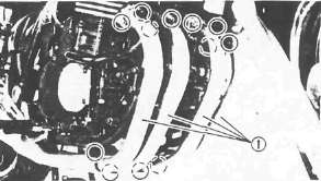
CYLINDER HEAD AND CYLINDER
1. Remove the cylinder head cover
NOTE:
Piston and cylinder can be removed, when necessary, without removing the camshaft.

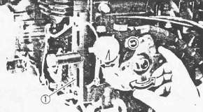
The main steps are as follows.
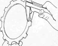
• Disconnect the cam chain using Cam Chain Cutter 1 (90890-01112).

• Remove the cylinder head nuts in the camshaft case using Hexagon Wrench 2 .
• Remove the cam shaft, cam shaft case and cylinder head as assembly.
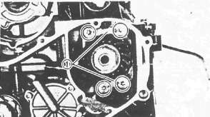
2. Remove:
• Cam chain guide (Upper) 1
• Camshaft cap (I3) 2
• Camshaft cap (E3) 3
• Dowel pins

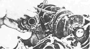
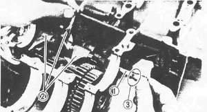
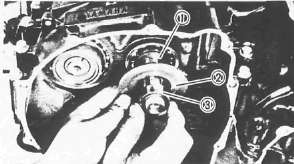
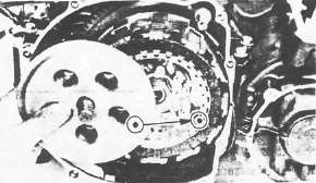
3. Remove:
• Cam chain sprocket bolts 1 Use 2 2 mm (0.88 in) wrench to hold camshaft.
• Camshaft caps (I1, I2, I4, E1,E2, E4)
• Dowel pins
• Camshafts
• Cam chain guide (Front) 1
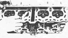
4. Remove:
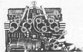
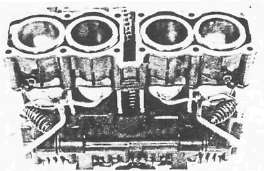
• Cylinder head nut
• Cylinder head
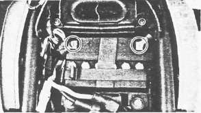
NOTE:
Follow the numerical order shown in photo, start by loosening each nut 1 /4 turn until all are loose.

5. Remove:
• Cylinder head gasket 1
• Dowel pins 2
• Cylinder
• Oil delivery pipes 3
• Cylinder base gasket
• Dowel pins
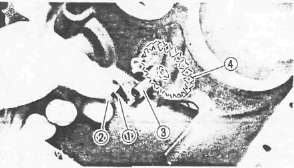
Pistons, Starter, Generator and Pickup Coil
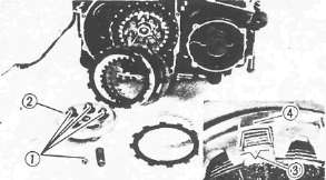
Pistons, Starter, Generator and Pickup CoilPISTON AND CAM CHAIN GUIDE
Mark each piston so it can be reinstalled in the appropriate cylinder.
1. Remove:
• Piston pin clips 1
• Piston pins 2
NOTE: Before removing the piston pin clip, cover the crankcase with a clean rag so you will not accidentally drop the clip into the crankcase.

• Pistons
• Cam chain guide (Rear) 3
STARTER MOTOR AND GENERATOR

1. Remove:
• Starter motor bolts
• Starter motor assembly 1
• Generator cover 2
2. Remove:
• Stator coil 1
• Gasket 2

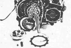
3. Attach the rotor Holding Tool (90890-04043) 1
4. Remove the rotor holding bolt 2

5. Attach:
• Rotor Puller Adapter (90890-04052) 1
• Rotor Puller (90890-01080) 2
6. Remove the rotor 3
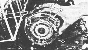
PICKUP COIL

1. Disconnect:
• Oil level switch lead 1
• Neutral switch lead 2
• Pickup coil lead (from clamps 3 )

2. Remove:
• Timing plate 1
• Dowel pin 2
• Pickup coil assembly 3
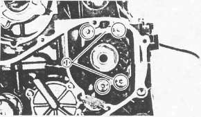
Clutch and Oil Pump
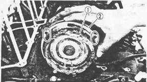
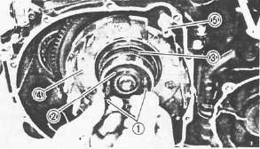
Clutch and Oil PumpCLUTCH
1. Remove:
• Water pump drive sprocket cover 1
• Water pump drive sprocket 2
Note:
Water pump drive sprocket bolts 3 is locked with LOCTITE®.
• Spacer
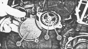
2. Remove:
• Bearing retaining washer 1
• Clutch cover
• Gasket
• Dowel pins
3. Remove:
• Clutch spring bolts 1
• Clutch springs
• Pressure plate 2
• Friction plates
• Clutch plates
NOTE:
The outermost friction plate has a tab with a V-cut 3 in it. Give some identifying mark to the corresponding dog 4 in the clutch housing. This dog is narrowest.

4. Bend the lock washer tab 1
5. Attach the universal Clutch Holder (90890-04086) 2

6. Remove:
• Clutch boss nut 1
• Lock washer 2
• Clutch boss 3
• Thrust washer 4
• Oil baffle plate 5
7. Install:
• Clutch cover bolts 1 (into clutch housing spacer holes)
8. Remove:
• Clutch housing spacer 2
• Bearing 3
• Clutch housing 4
• Water pump drive shaft 5
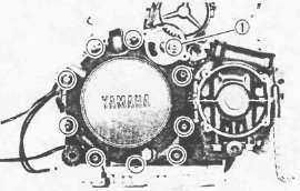
OIL PUMP
1. Remove:
• Oil filter
• Oil level switch 1
• Oil pan
• Clamps 2
• Gasket
• Dowel pins

2. Remove:
• Oil pump drive chain cover 1
• Oil pump assembly 2

3. Remove:
• Oil pump drive sprocket 1
• Chain 2
• Collar 3
• Thrust plate 4
Shifter, Middle Gear and Crankcase
Shifter, Middle Gear and CrankcaseSHIFTER AND MIDDLE GEAR

1. Remove:
• Crankcase cover (Left) 1
• Gasket
• Dowel pin 2
• Shift shaft 3
• Shift lever 4
• Oil level maintaining plug 5

2. Remove:
• Middle driven gear housing 1
• Shims 2
3. Remove:
• Bearing retainer 1 Use Torx Driver #40 (90890-04049).
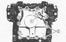
CRANKCASE
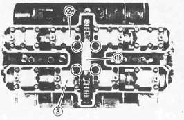
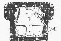
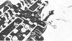
1. Remove:
• Bolts (Crankcase)
• Clamps
• Battery negative lead
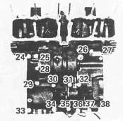
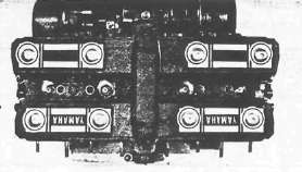
NOTE:
• Remove the bolts starting with the highest numbered one.
• The embossed numbers in the crankcase designate the crankcase tightening sequence.
Upper crankcase

Lower crankcase
2. Remove:
• Lower crankcase
• Blind plug (from crankcase right end)
• Crankshaft bearings
NOTE:
Identify each crankshaft bearing position very carefully so that it can be reinstalled in its original place.
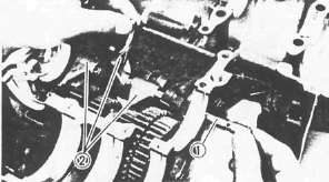
Gears, Starter Drive and Shift Drum
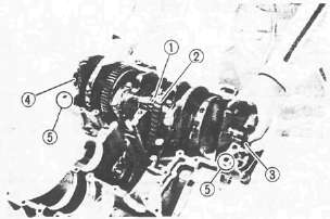
Gears, Starter Drive and Shift DrumMAIN AXLE AND MIDDLE DRIVE GEAR

1. Remove:
• Middle drive gear 1
• Main axle 2
• Bearing 3
• Dowel pins 4
• O-ring 5
A.C.G. SHAFT, STARTER DRIVE, AND CRANKSHAFT

1. Remove housing using Torx Driver #30 (90890-05245)

2. Remove:
• Oil spray nozzle 1
• A.C.G. shaft 2
Use Armature Shock Puller (90890-01290) and (90890-01291)3
3. Remove:
• Starter clutch assembly 1
• Crankshaft
5. Bend the lock washer tab 1
6. Remove:
• Starter idle gear shaft bolt 2
• Lock washer
• Stopper plate
• Starter idle gear shaft 3
• Starter idle gear 4
SHIFT CAM AND DRIVE AXLE
1. Remove:
• Guide bar 1
• Shift forks 2

2. Remove:
• Neutral switch 1
• Bolts 2
• Stopper plate 3
• Shift cam locating pin 4
• Shift cam 5

3. Remove:
• Drive axle bearing cover 1
• 5th wheel gear 2
4. Remove the drive axle assembly
Inspection and Repair
Inspection and RepairCylinder Head and Camshaft Case
Cylinder Head and Camshaft Case 
1. Remove
• Lifters 1
• Valve pads 2
NOTE:
Identify each lifter and pad position very carefully so that it can be reinstalled in its original place.
2. Measure the warpage using a precision straight edge or surface plate and feeler gauges. Resurface if warpage exceeds allowable limit.
Cylinder Head Warpage: Less than 0.03 mm (0.0012 in)

3. Remove the camshaft case 1

4. Remove:
• Camshaft case gasket 1
• Dowels 2
• Cylinder head nuts
• Plain washers

5. Attach:
• Valve Spring Compressor (90890-04019) 1
• Attachment (90890-04108) 2

6. Remove:
• Valve retainers 1
• Valve spring seat 2
• Valve spring 3
• Oil seal 4
• Valve spring seat 5
• Valve 6
NOTE:
Deburr any deformed valve stem end. Use an oil stone to smooth the stem end.
1 Deburr 2 Valve stem
7. Eliminate:
• Carbon deposit (from combustion chamber) Use rounded scraper.
NOTE:
Do not use a sharp instrument and avoid damaging or scratching:
• Spark plug threads
• Valve seat
• Aluminum
8. Install:
• Valves
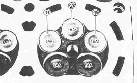
NOTE:
Be sure the "1AA : " mark 1 valves are for intake left and right and "1AA •" mark 2 for intake center.
9. Install the valve springs

NOTE:
• All valve springs must be installed with the larger pitch 1 upward as shown.
• Be sure the "Blue" spring is for intake and "Red" for exhaust.
2 Smaller pitch

10. Install:
• Dowels 1
• Camshaft case gasket 2
NOTE:
Be sure the "UP" mark face to upward.
• Plain washers 3
• Cylinder head nuts 4

11. Install the camshaft case 1. Torque the camshaft case bolts to 10 Nm (1.0m-kg, 7.2ft-ft)
Valves, Guides, Seats and Springs
Valves, Guides, Seats and Springs1. Measure the valve stem clearance


Use a bore gauge 3 to determine the valve guide inside diameter.
Valve Guide Inside Diameter Limit: 5.05 mm (0.199 in)
2. Measure the valve stem diameter with a micrometer. Replace guide if clearance exceeds specification.
Valve stem clearance = Valve guide inside diameter 1 minus Valve stem diameter 2
Valve Stem Clearance Limit:
Intake 0.08 mm (0.003 in)
Exhaust 0,10 mm (0.004 in)
3. Examine the valve face for pitting or wear and regrind as necessary. Measure the valve face as indicated below and replace if valve cannot be brought back to specification.

Minimum Thickness (Service limit) 1 : 0.7 mm (0.028 in)
Beveled 2 : 0.35 mm (0.014 in)
Minimum Length (Service limit) 3 :14.5 mm (0.6 in)

4. Check:
• Valve stem end Mushroom shape and/or diameter. Replace if larger than rest or stem.
• Runout. Replace if it exceeds specification.
Maximum Valve Stem Runout: 0.01 mm (0.0004 in)
5. Inspect the valve guide for signs of wear and/or oil leakage. Replace if excessive.
NOTE:
Heat the
cylinder head in an oven to 100°C (212°F) to ease valve guide removal
and reinstallation and to maintain correct interference fit.

Valve Guide Replacement
1. Remove the valve guide. Use Valve Guide remover 1 (90890-04097)
NOTE
• Always replace valve guide if valve is replaced.
• Always replace oil seal if valve is removed.

2. Install the new valve guide with Valve Guide Installer 1 (90890-04098) and Valve Guide Remover (90890-04097).

3. Bore valve guide 1 to obtain proper valve stem clearance. Use 5 .0 mm (0.20 in) Reamer 2 (YM-04099).
Valve Seat
1. Inspect the valve seat for pitting/wear. Cut new faces as required.

2. Measure the valve seat width 1. Follow the next steps if out of specification.
|
|
Standard width |
Wear limit |
|
Valve seat width |
1.0 ± 0.1 mm (0.040 ± 0.004 in) |
1.8 mm (0.070 in) |
3. Apply:
• Mechanic's bluing dye (Dykem) (to valve and seat)
• Fine grinding compound (Small amount) (to valve face surface)
4. Position the valve into the cylinder head.
CAUTION:
Do not allow any compound to contact the valve stem or guide. Flush thoroughly as required.

5. Spin it rapidly back and forth, then lift valve and clean off all grinding compound.
6. Inspect the valve seat surface. Wherever valve seat and valve face made contact, blueing will have been removed.

7. Measure:
• Valve seat width 1
• Contacting position 2
Recut if out of specification.
Width 1 : 1.0 ± 0.1 mm (0.040 ± 0.004 in)
Position 2 : 0.3 mm (0.012 in)
8. Cut valve seat.
NOTE:
Cut valve seat using valve seat cutter 1 if valve seat width exceeds limit or if valve seat is pitted or worn.
CAUTION:
When twisting cutter, keep an even downward pressure to prevent chatter marks.
Valve seat recutting steps are necessary if:
• Valve seat is uniform around perimeter of valve face but too wide or too narrow or not desired position on valve face.

|
Cut valve seat as follows: |
|
|
Section A |
20° Cutter |
|
Section B |
45° Cutter |
|
Section C |
60° Cutter |

|
• Valve face indicates that valve seat is in desired position 1 but too wide |
||
|
Valve seat cutter set |
Desired result |
|
|
Use |
20° Cutter 6 0° Cutter |
to reduce valve seat width. |

|
• Valve seat is desired position 2 but too narrow |
||
|
Valve seat cutter set |
Desired result |
|
|
Use |
45° Cutter |
to achieve a uniform valve seat width (Standard specifications). |
|
• Valve seat is too narrow and touching the valve margin 3. |
||
|
Valve seat cutter set |
Desired result |
|
|
Use |
20° Cutter, first 45 ° Cutter |
to obtain correct seat width. |

|
• Valve seat is too narrow and touching the bottom edge of the valve face 4. |
||
|
Valve seat cutter set |
Desired result |
|
|
Use |
60° Cutter, first 45 ° Cutter |
to obtain correct seat width. |
NOTE:
Lap valve/valve seat assembly if:
•Valve face/valve seat are used or severely worn.
•Valve and valve guide has been replaced.
•Valve seat has been cut.
Valve/Valve Seat Assembly Lapping
1. Apply coarse lapping compound (Small amount!) to valve face.
2. Position the valve (in cylinder head)

3. Rotate the valve. Turn until valve and valve seat are evenly polished, then clean off compound.
4. Repeat above steps with fine compound and continue lapping until valve face shows a completely smooth surface uniformly.
5. Eliminate all compound from valve face.
6. Apply mechanic's bluing dye (Dykem) 1 to valve face and seat.
7. Rotate the valve. Valve must make full seat contact indicated by grey surface all around valve face where bluing was removed.
8. Apply solvent into each intake and exhaust port. If solvent leaks past valve seat, relap until seal is complete.
NOTE:
Pour solvent into intake and exhaust ports only after completion of all valve work and assembly of head parts.
Re-lapping steps:
• Disassemble head parts.
• Repeat lapping steps using fine lapping compound.
• Clean all parts thoroughly.
• Reassemble and check for leakage again using solvent.
• Repeat steps as often as necessary to effect a satisfactory seal.

Valve Spring Measurement
Measure the valve spring free length. Replace if out of specification.
Valve Spring Free Length (Limit):
|
lntake Spring |
Exhaust Spring |
|
|
37.76 mm (1.487 in) |
37.96 mm (1.495 in) |
|

2. Measure:
• Installed length 1
• Valve spring installed force 2
Replace if out of specification.
Valve Spring Installed Force:
|
Intake Spring |
Exhaust Spring |
||
|
1 |
2 |
1 |
2 |
|
35.0 mm |
7.3-8.7 kg |
35.0 mm |
11.0-13.0 kg |
Camshafts, Chain and Sprockets
Camshafts, Chain and SprocketsCAMSHAFT, CAM CHAIN, AND CAM SPROCKET

Camshaft
1. Measure:
• Large cam lobe length 1
• Small cam lobe length 2
Use a micrometer. Replace if out of specification.
|
|
Intake [Limit] |
Exhaust [Limit] |
|
1 |
32.45 mm (1.2776 in) |
32.30 mm (1.2727 in) |
|
2 |
24.85 mm (0.9783 in) |
24.85 mm (0.9783 in) |
Camshaft/Cap Clearance Measurement
1. Install:
• Intake camshaft
• Exhaust camshaft
2. Position a strip of Plastigage® (YU-33210) 1 onto camshaft.
3. Install the camshaft caps 1
4. Tighten the camshaft cap bolts
Camshaft Cap Bolts: 10 Nm (1.0mkg, 7.2ft-lb)
NOTE:
Do not turn the camshaft when measuring clearance with Plastigage.
5. Remove the camshaft caps

6. Measure the width of Plastigage® 1
Out of specification -> Follow step 7 .
Camshaft-to-cap Clearance: 0.050 - 0.084 mm (0.0020- 0.0033 in)
7. Measure the camshaft bearing surface diameter 1. Use a micrometer.
Out of specification -> Replace camshaft.
Within specification -> Replace cylinder head.
Camshaft Bearing Surface Diameter:
Standard: 24.437~24.450mm (0.9621-0.9626 in)
Cam Cap Inside Diameter: Standard: 2 4 .500-24.521 mm (0.9646-0.9654 in)
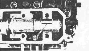
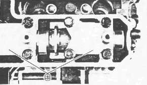
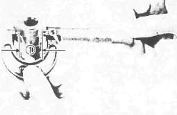
Cam Chain Tensioner
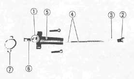
1 One way cam
2 End plug
3 Washer
4 Spring
5 Tensioner body
6 Tensioner rod
7 Gasket
1. Check the one-way cam operation. Replace if operation is not smooth.
2. Inspect: all parts for damage and wear. Replace as necessary.
Cam Chain
1. Inspect:
• Cam chain
Chain stretch/Cracks-> Replace
Cam Sprockets
1. Inspect the cam sprockets for wear/damage. Replace worn sprockets.

Chain Guide
1. Inspect:
• Upper chain guide 1
• Exhaust side chain guide 2
• Intake side chain guide 3
Replace worn parts.
Cylinders, Pistons and Rings
Cylinders, Pistons and RingsCYLINDER
1. Inspect the cylinder walls for vertical scratches and Rebore or Replace cylinder as required.

2. Measure the cylinder inside diameter.
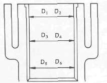
NOTE:
Obtain measurements at three depths by placing measuring instrument parallel to and at right angles to crankshaft.
Out of specification -> Rebore cylinder, and replace piston and piston rings.
|
|
Standard |
Wear Limit |
|
Cylinder bore: C |
68.000-68.005 mm |
68.1 mm |
|
Cylinder taper: T |
0 |
0.05 mm |
C= Maximum D
T= Maximum of D1or D2 minus Minimum of D5 or D6
PISTON, PISTON RING, AND PISTON PIN

Piston 1 . Measure the piston skirt diameter "P" 2
NOTE:
Measure the piston skirt diameter where the distance 1 is 5.0 mm (0.197 in) from the piston bottom edge.
|
|
Piston Size P |
|
Standard |
68.00 mm |
|
Oversize 2 |
68.50 mm |
|
Oversize 4 |
69.00 mm |
2. Measure the piston clearance
Piston Clearance = Cylinder inside diameter "C" minus Piston skirt diameter "P"
Out of specification -> Rebore cylinder, and replace piston and piston rings.
Piston Clearance: 0.06 - 0.08 mm (0.0024 - 0.0031 in)

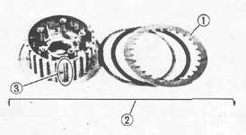
Piston Ring 1 .
Measure ring side clearance. Use a feeler gauge.
Out of specification -> Replace piston.
NOTE:
Clean carbon from piston ring grooves and rings before measuring side clearance.
|
|
Piston Ring Side Clearance (Limit): |
|
|
Top Ring |
0.15 mm (0.006 in) |
|
|
2nd Ring |
0.15 mm (0.006 in) |
|
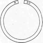
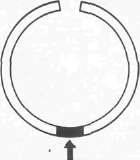
2. Position the piston ring in cylinder.
NOTE:
Insert a ring into cylinder, and push it approximately 2 0 mm (0.8 in) into cylinder. Push ring with piston crown so that ring will be at a right angle to cylinder bore.

3. Measure the ring end gap. Replace if out of specification.
NOTE:
You cannot measure end gap on expander spacer of oil control ring. If oil control ring rails show excessive gap, replace all three rings.
|
|
End Gap Limit (Installed): |
|
Top Ring |
1.0 mm (0.040 in) |
|
2nd Ring |
1.0 mm (0.040 in) |
|
Oil Ring |
1.5 mm (0.060 in) |
Piston Ring Oversize
•Top and 2 nd piston ring Oversize top and middle ring sizes are stamped on top of ring.
|
Oversize 2 |
0.50 mm (0.0197 in) |
|
Oversize 4 |
1.00 mm (0.0394 in) |
• Oil control ring Expander spacer of bottom ring (oil control ring) is color-coded to identify sizes.
|
Size |
Color |
|
Oversize 2 |
Red |
|
Oversize 4 |
Yellow |
Piston Pin
1. Lubricate piston pin (Lightly)

2. Install:
• Piston pin 1 into small end of connecting rod 2.
3. Check for free play
Free play -> Inspect connecting rod for wear.
Wear -> Replace connecting rod and piston pin.

4. Position the piston pin 1 into piston.
5. Check for free play in piston.
Free play -> Replace piston pin and/or piston.
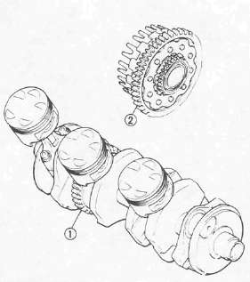
Crankshaft and Connecting Rods
Crankshaft and Connecting RodsCRANKSHAFT AND CONNECTING ROD

Crankshaft Runout
1. Place both ends of crankshaft on V-blocks.
2. Rotate Crankshaft
3. Measure the crankshaft runout at main journal bearings. Use a Dial Gauge (90890-03097).
Maximum Crankshaft Runout: 0.03 mm (0.0012 in)
Connecting Rod Bearings
1 . Inspect bearings for Burns/Flaking/Roughness/Scratches. Replace as necessary.
Connecting Rod Bearing Clearance
1. Clean all parts thoroughly.

2. Install connecting rod bearings 1 into connecting rod and cap.
3. Attach Plastigage® 2 onto crankpin.
4. Position:
• Connecting rod 3 onto crankshaft.
• Connecting rod cap 4

NOTE:
• Be sure the "Y" marks 1 on the connecting rods face toward left crankshaft end.
• Be sure the letters on both components align to form a perfect character.
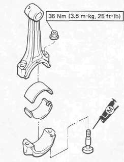
5. Apply:
Molybdenum disulfide grease (to bolt threads)
Torque both ends of rod cap evenly.
NOTE:
Do not move connecting rod until a clearance measurement has been completed.
CAUTION:
Tighten to full torque specification without pausing. Apply continuous torque between 2.0 and 3.6 m-kg. Once you reach 2.0 m-kg DO NOT STOP TIGHTENING until final torque is reached. If tightening is interrupted between 2.0 and 3.6 m-kg, loosen nut to less than 2.0 m-kg and start again.
Connecting Rod Cap: 3 6 Nm (3.6 m-kg, 26 ft-lb)
6. Remove connecting rod cap carefully.

7. Measure Plastigage® width 1 . Replace connecting rod bearing if clearance is excessive.
Connecting Rod Bearing Clearance: 0.032 ~ 0.056 mm (0.0013- 0.0022 in)
Crankshaft Main Bearing Clearance Measurement
1. Clean all parts.
2. Position upper crankcase half. Place on a bench in an upside down position.
3. Install:
• Bearings into the upper crankcase
• Crankshaft
4. Attach Plastigage® (YU-33210) 1 onto the crankshaft journal surface.
NOTE:
Do not move crankshaft until clearance measurement has been completed
5. Install:
• Bearings into lower crankcase
• Lower crankcase
6. Tighten bolts

CAUTION:
Tighten to full torque in torque sequence cast on the crankcase.
9 mm (0.36 in) Bolt: 3 6 Nm (3.6m-kg, 2 5 fMb)
7. Remove bolts in reverse assembly order. carefully remove lower crankcase.
8. Measure Plastigage® width 1
Out of specification -> Replace bearings. Replace crankshaft if necessary.
Main Bearing Oil Clearance: 0.020 - 0.044 mm (0.0008-0.0017 in)
Crankshaft Main and Connecting Rod Bearing Selection

• Numbers used to indicate crankshaft journal sizes are stamped on the LH crankweb. The first five are main bearing journal numbers, starting with the left journal. The four rod bearing journal numbers follow in the same sequence.

• The upper crankcase half is numbered J1, J2, J3, J4, and J5 on the rear right boss as shown.
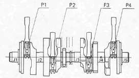
•The connecting rods are numbered 4 or 5 .
The numbers are stamped in ink on the rod cap 1.
|
Bearing Color Code |
|
|
No. 1 |
Blue |
|
No. 2 |
Black |
|
No. 3 |
Brown |
|
No. 4 |
Green |
|
No. 5 |
Yellow |
* No. 5 applies only to the crankshaft main bearing selection.
Example, Selection of the crankshaft main bearing:
If the crankcase J1 and crankshaft J1 sizes are No. 4 and No. 1 , respectively, the bearing size No. is:
Bearing size No. = Crankcase No. minus Crankshaft No.
= 4 -1 = 3 (Brown)
Example 2 , Selection of the connecting rod bearing:
If the connecting rod P1 and crankshaft P1 sizes are No. 4 and No. 1 , respectively, the bearing size No. is:
Bearing size No. = Connecting rod No. minus- Crankshaft No.
= 4 -1 = 3 (Brown)
Oil Pump, Primary Drive and Starter Drive
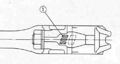
Oil Pump, Primary Drive and Starter DriveOIL PUMP

1. Remove:
•Screw
• Pump cover 1
• Pump shaft 2
• Pin 3
• Inner rotor 4
• Outer rotor 5
• Spring 6
• Relief valve 7
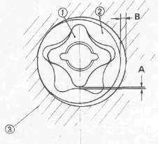
2. Measure:
•Clearance "A" (between inner rotor 1 and outer rotor 2
• Clearance "B" (between outer rotor 2 and pump housing 3 )
Out of specification -> Replace oil pump.
|
|
Oil Pump Clearance: |
Clearance A |
0.03 ~ 0.09 mm (0.0012- 0.0035 in) |
Clearance B |
0.03 ~ 0.08 mm (0.0012- 0.0031 in) |
PRIMARY DRIVE
1. Inspect:
• Primary drive gear 1
• Primary driven gear2
Wear/Damage -> Replace both gears,
Excessive noises during operation-► Replace both gears.
|
Primary Reduction Ratio: |
No. of teeth |
Ratio |
Drive |
Driven |
58 |
97 |
1.672 |
STARTER DRIVE

Electric Starter Clutch
1. Check:
• Roller 1 operation
• Spring 2 operation
• Spring cap 3 operation
Unsmooth operation -> Replace one-way clutch.
2. Inspect:
• Surface 4 of the idle gear
Pitting/Wear/Damage -> Replace.

Starter Clutch Shaft (A.C.G. shaft)
1. Check:
• Shaft 1
• Oil seal 2
Wear/Damage — Replace.
• Bearing 3
Unsmooth operation - Replace.
Clutch
ClutchCLUTCH

1. Inspect:
• Clutch housing dogs 1
Cracks/Pitting (edges): Moderate -> Deburr.
Severe -> Replace clutch housing.
2. Inspect
• Clutch housing bearing 2
• Spacer 3
Damage -> Replace.
NOTE:
The clutch boss contains a built-in damper beneath the first clutch friction plate (clutch plate 1). It is not necessary to remove the wire circlip 2 and disassemble the built-in damper unless there is serious clutch chattering.
3. Inspect the clutch boss spline 3 for pitting:
Moderate -» Deburr.
Severe -> Replace.

4. Place clutch plate on surface plane. For each plate:
Use feeler gauge 1 to measure maximum warpage from surface. Measure Friction plate thickness
Out of specification -> Replace clutch or friction plate as a set.
|
|
Standard |
Wear Limit |
|
Friction Plate Thickness |
3.0 mm (0.12 in) |
2.8 mm (0.11 in) |
|
Clutch Plate Warp Limit |
0 |
0.05 mm 0.0020 in) |

5. Inspect:
• Pressure plate
• Plate washer 1
•Thrust bearing 2
• Pull rod 3
Damage -> Replace.

6. Measure each clutch spring free length
If any are out of specification -> Replace springs as a set.
Clutch Spring Minimum Free Length 1 : 49.0 mm (1.93 in)
Transmission
TransmissionTRANSMISSION

1. Inspect:
• Shift fork cam follower 1
• Shift fork pawl 2
• Guide bar 3
Scoring/Bends/Wear-> Replace.

2. Inspect:
• Shift cam groove
• Shift cam dowel and side plate 1
• Shift cam stopper plate 2
• Neutral point 3
Wear/Damage -> Replace.

3. Measure the transmission shaft runout. Use a centering device and dial gauge. Replace shaft if bent.
Maximum Runout: 0.08 mm (0.0031 in)

4. Inspect the gear teeth 1 for: Blue discoloration/Pitting/Wear. Inspect the mated dogs 2 for Rounded edges/Cracks/Missing portions. Replace as necessary.
Note:
Minor rounding of the dogs can be corrected by undercutting. See the article on "Repairing second gear" elsewhere on this site.

5. Check:
• Proper gear engagement (Each gear to its counter part). Incorrect-> Reassemble.
• Gear and bearing movement. Roughness-> Replace.
SHIFTER
1. Inspect:
• Shift return spring 1
• Stopper lever spring 2
• Shift lever spring 3
Damage -> Replace.
• Shift shaft 4
• Shift lever 5
Damage/Bends/Wear -> Replace.
CRANKCASE
1. Inspect:
• Case halves
• Bearing seat
• Fitting
Damage -> Replace.
BEARINGS AND OIL SEALS
1. Inspect each bearing. Clean and lubricate, then rotate inner race with finger.
Roughness -> Replace bearing (see Removal).
2. Inspect all oil seals. Replace any damaged or worn seals.
CIRCLIPS AND WASHERS
1. Inspect:
• Circlips
• Washers
Damage/Looseness/Bends -> Replace.
Engine Assembly and Adjustment
Engine Assembly and AdjustmentLower Crankcase
Lower CrankcaseLOWER CRANKCASE

1 Drive axle assembly
2 5 th wheel gear
3 O-ring
4 Housing
5 Shift cam
6 Shift cam locating pin
7 Shift fork 3
8 Shift fork 2
9 Shift fork 1
10 Shift fork guide bar
11 Circlip
12 Dowel pin
13 Blind plug
14 Middle drive gear assembly

1. Install:
• Drive axle assembly 1
• 5th wheel gear 2
• new O-ring 3 onto the housing 4
• Drive axle bearing housing 4
Drive Axle Bearing Housing: 12 Nm (1.2 m kg, 8 .7 ft-lb)

2. Install:
• Shift cam 1
• Shift cam locating pin 2
• Stopper plate 3
• Bolt
• Neutral switch 4
Shift Cam Locating Pin: 8 Nm (0.8 m-kg, 5 .8 ft-lb)
Neutral Switch: 20 Nm (2.0 m-kg, 14 ft-lb)
3. Install:
•Shift forks 2
•Guide bar 1
NOTE: • All
shift fork numbers should face the left side and be in sequence (1, 2 ,
3 ), starting from the left.
• The guide bar groove 3 should face the right side.
4. Place the shift cam and transmission gears in NEUTRAL position.
CAUTION:
Be sure the gear shifts correctly while hand-turning the shift cam.
5. Clean the crankcase counterbore where the main bearing is fitted.
6. Install the crankshaft bearings See inspection for crankshaft bearing selection.
CRANKSHAFT
1. Clean:
• Crankshaft
• Connecting rods
2. Install the connecting rod bearings into connecting rod and cap.
3. Lubricate the connecting rod bolt threads with Molybdenum Disulfide Grease
4. Apply engine oil to the crankshaft pins.
5. Install:
• Connecting rods
• Rod caps

NOTE:
• Be sure the letter on both components align to form a perfect character.
• The stamped "Y" mark on the connecting rods 1 should face towards the left side of the crankcase.
Upper Crankcase
Upper CrankcaseUPPER CRANKCASE

1 Crankshaft bearing
2 Drive chain guide
3 Starter idle gear
4 A.C.G. drive chain
5 Oil seal
6 Starter clutch assembly
7 Main axle assembly
8 A.C.G. shaft
9 O-ring
10 Oil spray nozzle
11 Housing
12 Cam chain guide
|
CONNECTING ROD BEARING SELECTION: |
|
|
CALCULATED NO. |
COLOR CODE |
|
1 |
BLUE |
|
2 |
BLACK |
|
3 |
BROWN |
|
4 |
GREEN |

1. Install:
• Crankshaft bearings 1
• Drive chain guide 2
• Starter idle gear 3
Drive Chain Guide: 8 Nm (0.8 m-kg, 5.8 ft-lb)
Starter Idle Gear: 8 Nm (0.8 m-kg, 5.8 ft-lb)
2. Apply engine oil to the bearings.
3. Place the cam chain 1 , drive chain 2 , and oil seal 3 onto the crankshaft.
4. Install the crankshaft (onto the upper crankcase)
NOTE:
• Insert the oil seal flange completely into the crankcase positioning groove.
•Be careful not to damage the oil seal duringinstallation.
• Blind plug 4
• Dowel pins 5
5. Place the drive chain on the starter clutch assembly.
6. Install
• Starter clutch assembly 1 onto the upper crankcase
• A.C.G. shaft
7. Install:
• Oil spray nozzle 1 with new O-ring 2
• Housing with new oil seal 3
NOTE:
Lightly apply grease to the oil seal lips.
Housing Bolt: 10 Nm (1.0 m-kg, 7.2 ft-lb) LOCTITE®

8. Install:
• O-ring (New) 1
• Dowel pins 2
• Half clips 3
• Main axle assembly 4
• Bearing 5
• Middle drive shaft assembly 6
9. Position the bearing pin (left bearing) as shown 7.
CRANKCASE ASSEMBLY

1. Attach a length of wire to the cam chain.
2. Apply Yamaha bond No. 1215 (908 8 5505).
NOTE:
DO NOT ALLOW any sealant to come in contact with the oil galley O-ring, or crankshaft bearings. Do not apply sealant to within 2-3 mm (0.08-0.12 in) of the bearings.
3. Install the lower crankcase onto the upper crankcase.

• Be sure the shift fork (No. 1 ) 1 engages the groove 2 in the 2nd pinion gear on the main axle.
• Insert the oil seal and blind seal flanges completely into the crankcase positioning grooves.
• Be careful not to damage the seals during installation.
4. Install:
• Bolts
• Washers
• Clamps
• Battery negative lead
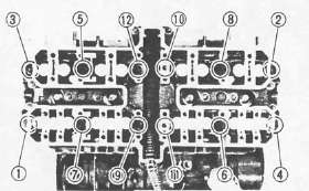
5. Tighten:
• Crankcase bolts
Crankcase:
6 mm bolt: 12 Nm (1.2m-kg, 8.7ft-lb)
8 mm bolt: 24 Nm(2.4m-kg, 17 ft-lb)
NOTE:
The embossed numbers in the crankcase designate the crankcase tightening sequence.

LOWER CRANKCASE
UPPER CRANKCASE
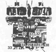
Oil Pump, Clutch and Water Pump
Oil Pump, Clutch and Water PumpOIL PUMP AND OIL PAN

1 Chain cover
2 Oil pump sprocket
3 Oil pump drive sprocket
4 Oil pump cover
5 Inner rotor
6 Spring
7 Relief valve
8 Shaft
9 Dowel pin
10 Outer rotor
11 Dowel pin
12 O-ring

1. Install:
• O-ring 1 onto the oil pump assembly
• Chain
• Oil pump assembly
• Chain cover
Oil Pump: 12 Nm (1.2 m-kg, 8.7 ft-lb)
2. Install:
• Oil pan
• Wire clamps 1
• Bolts
• Oil level switch 2
Oil Pan: 12 Nm (1.2 mkg, .7 ft-lb)
Oil Level Switch: 8 Nm (0.8m-kg, 5.8 ft-lb)
CLUTCH

1 Plate washer
2 Oil seal
3 Bearing
4 Pinion gear
5 Plate washer
6 Circlip
7 Lock washer
8 Friction plate
9 Clutch plate
10 Wire clip
11 Clutch plate
12 Clutch boss spring
13 Spring seat
14 Thrust plate
15 Spacer
16 Bearing (15-28)
17 Oil pump drive sprocket
18 Collar
19 Thrust plate
20 Pull rod
21 Bearing
22 Water pump drive shaft
23 Spacer
24 Water pump drive gear
Note:
The outermost friction plate has a V-cut in it. Give some identifying mark to the corresponding dog in the clutch housing.
CLUTCH AND OIL PUMP DRIVE SPROCKET
1. Install:
• Thrust plate 1
• Oil pump drive sprocket 2
12 Nm (1.2m-kg, 8.7 ft-lb)
2. Hook the drive chain on the drive sprocket.
3 Install:
• Collar 3
4. Install:
• Water pump drive shaft 1
• Clutch housing
CAUTION:
Be sure that the oil pump drive gear tabs engage the clutch housing grooves on its back or the tabs will be damaged when tightening the clutch boss securing nut.

5. Install:
• Bearing 1
• Spacer 2
• Thrust plate 3
• Clutch boss 4
• Lock washer (New) 5
• Nut 6
Clutch Boss: 70 Nm (7.0 m kg, 50 ft lb)
6. Bend lock washer tabs against the nut flats.
7. Install:
• Friction plates
• Clutch plates

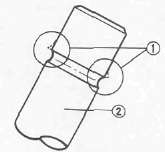
8. Install:
• Friction plate (with V-cut 1 in tab)
NOTE:
Install the friction plate so that the V-cut tab is in the identified dog 2 . If you forget to identify the position with a mark, measure the width of each dog. 13.8 mm (0.543 in) width is for that position. The other width are 14 mm (0.551 in).

9. Install:
• Plate washer 2
• Thrust bearing 3 onto the pull rod 4
• Pull rod 4 into the pressure plate 1
10. Install:
• Pressure plate
NOTE:
Align a dot on the clutch boss with a dot on the pressure plate.
• Clutch springs
Clutch Spring: 8 Nm (0.8 m-kg, 5.8 ft-lb)
11. Install:
• Oil baffle plate
• Dowel pins
• Gasket
• Clutch cover

NOTE:
Set the gear of the clutch pull rod facing approximately 45° from horizontal toward the rear.

• Set the clutch lever 1 on the right crankcase cover parallel to the gasket surface.
• Make sure that the punch mark on the lever 2 align with the mark on the crankcase cover 3 when pushing the lever towards the front by hand.
Clutch Cover: 1 2 Nm(1.2m-kg,8.7ft-lb)

12. Install:
• Spacer 1
• Water pump drive gear 2
• Water pump drive gear cover.
Water Pump Drive Gear: 12 Nm (1.2 m-kg, 8.7 ft-lb) LOCTITE®
Cover: 8Nm(0.8m-kg, 5.8ft-lb)
Middle Gear, Generator, Starter and Pickup Coil
Middle Gear, Generator, Starter and Pickup CoilMIDDLE GEAR
1. Install:
• Bearing retainers 1
• TORX screws (New)
• Oil level maintaining plug
Bearing Retainer: 25 Nm (2.5 m-kg, 18 ft-lb)
2. Stake the screw heads to the dents on the bearing retainers with a center punch.

3. Install:
• Shims 1
• Middle driven gear housing 2
• Bolt
Middle Driven Gear Housing: 25 Nm (2.5 m-kg, 18 ft-lb). Use LOCTITE®
SHIFTER

1. Install:
• Washer 1
• Shift shaft 2
• Shift lever3
• Oil level maintaining plug 4
• Gasket

2. Install:
• Crankcase cover
• Wire harness clip 1
• Bolts
Crankcase Cover: 12 Nm (1.2 m-kg, 8.4 ftlb)
GENERATOR AND STARTER

1. Install:
• Rotor Use Rotor Holding Tool (90890-04043) 1 .
Rotor: 55 Nm (5.5 m-kg, 40 ft-lb)
2. Install the stator coil 1
NOTE:
Align the grooves on the stator coil core with the bolt holes on the crankcase.
• Gasket 2
• A.C.G. cover
A.C.G. Cover: 12 Nm (1.2 mkg, 8 .4 ft-lb)

3. Install:
• Starter motor
• Bolts
Starter Motor: 7 Nm (0.7m-kg, 5 .1 ft-lb)
NOTE:
• Be careful the O-ring 1 is not damaged when installing the starter motor.
• Route the A.C.G. lead wires 2 as shown.
PICKUP COIL

1. Install:
• Pickup coil assembly
• Timing plate
NOTE: Align the locating pin on the crankshaft with the corresponding slot in the timing plate.
Pickup Bolt: 8 Nm (0.8 m-kg, 5.8 ft-lb)
Timing Plate: 24 Nm (2.4 m-kg, 17 ft-lb)
Pistons and Cylinder
Pistons and CylinderPISTON AND CYLINDER
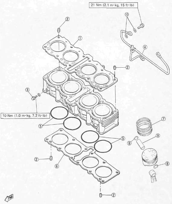
1 Cylinder head gasket
2 Dowel pin
3 Drain bolt
4 Oil delivery pipe
5 O-ring
6 Cylinder base gasket
7 Piston ring
8 Piston pin clip
9 Piston pin
10 Copper washer
1. Install:
• Piston rings (onto the pistons)
NOTE:
Be sure to install the rings so that Manufacturer's marks or numbers are located on the top side of the rings. Oil the pistons and rings liberally.
2. Install pistons.

NOTE:
• Be sure the piston is positioned correctly.
• Always install new piston pin clips 1
• The "EX" mark 2 on the piston should face toward the front (Exhaust side).
3. Oil liberally:
• Pistons
• Rings
• Cylinders
4. Set piston ring ends as per the above diagram.
CAUTION:
Make sure the ends of the oil ring expanders do not overlap.
1 TOP
2 OIL RING (LOWER RAIL)
3 OIL RING (UPPER RAIL)
4 2ND

5. Install:
• Cam chain guide (Rear) 1
Cam Chain Guide (Rear): 10 Nm (1.0m-kg, 7.2ft-lb)
6. Check guide movement. Reassemble if the action is not smooth.
7. Install:
• Dowel pins
• Gasket (New)
• Cylinder
CAUTION:
• Be careful not to damage the cam chain guide during installation.
• Pass the cam chain through the cam chain cavity.

8. Position oil delivery pipe 1
9. Set the dial gauge on the No. 1 piston head center as shown to find the No. 1 piston top dead center and check whether the "T" mark on the timing plate and stationary pointer are aligned or not. If not, loosen the pointer securing screw and adjust.
Cylinder Head
Cylinder HeadCYLINDER HEAD

1 Check bolt
2 Dowel pin
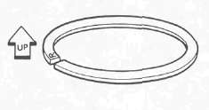
3 Camshaft case gasket
4 Valve guide
5 O-ring
6 Camshaft case
7 Cylinder head
8 Oil pipe
[A] Be sure the "UP" mark faces upward.

1. Install:
• Dowel pins 1
• Cylinder head gasket (New)
• Cylinder head
NOTE:
• Be careful not to damage the cam chain guide during installation.
• Pass the cam chain through the cam chain cavity.

2. Tighten nuts in sequence as shown and torque the nut in two stages.
Cylinder Head: [10 mm ] 37 Nm (3.7 m-kg, 27 ft-lb)
3. Install the cam chain guide (Front) 1
NOTE:
The lower end of chain guide must rest in the cam chain guide slot in the crankcase.
Camshafts
CamshaftsCAMSHAFT

1 Cam cap
2 Dowel pin
3 Cam chain sprocket (IN)
4 Cam chain sprocket (EX)
5 Camshaft (IN)
6 Camshaft (EX)
7 Lifter
8 Adjusting pad
9 Cam chain guide (Front)
10 Oil delivery pipe
11 Copper washer
12 Camchain tensioner
13 Camchain tensioner end cap bolt
14 Camchain guide (Upper)
15 Valve retainer
16 Spring seat
17 Valve spring
18 Spring seat
19 Oil seal
20 Valve

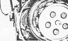
* When installing the sprocket, use holes except for the one with a punch mark.
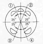
Flywheel is marked as follows:

(1) Pickup coil mark
(2) TDC for No. 1 cylinder
(3) Firing range for the No. 1 cylinder
Camshaft installing steps:
• Align the "T" mark on the timing plate 2 with the stationary pointer 1 . Do not turn the crankshaft during the camshafts installation.
• Install the cam chain sprockets onto the camshafts.
• Apply engine oil to the camshaft bearing surface.

• Turn the camshafts by hand so that the timing marks 3 (o: small hole) on the camshafts face upward.
• Install the dowel pins into the cam caps.
• Install the caps (without IN3 and EX3) onto the camshafts and tighten the cap bolts.
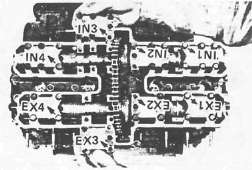
NOTE:
• The arrow mark on the caps should face toward the outside.
• The numbers are punched on the camshaft caps in increments from left to right.
Cam Cap: 10 Nm (1.0m-kg, 7.2 ft-lb)
2. Install cam chain sprockets
Cam chain sprockets installing steps:
• Align the "T" mark on the timing plate 2 with the stationary pointer on the pickup coil 1 . Do not turn the crankshaft when installing the sprockets.
• Place the cam chain onto the exhaust sprocket.

• Install the sprockets and finger tighten the sprocket bolts 3
NOTE:
When installing the sprocket, use holes except for the one with a punch mark 4.

• Rotate the exhaust camshaft to align the punched mark on the camshaft 5 with the "—" mark on the EX2 cam cap 6
• Force the exhaust camshaft clockwise to remove the cam chain slack.
• Place the cam chain onto the intake sprocket.
• Install the sprocket and finger tighten the sprocket bolt.

• Rotate the intake camshaft to align the punched mark on the camshaft with the "—" mark on the IN2 cam cap.
• Force the intake camshaft clockwise to remove all the cam chain slack.
• Insert your finger into the cam chain tensioner hole, and push the cam chain guide inward 7.
•While pushing the cam chain guide, be sure camshaft timing marks align with the cap marks.
• Remove the intake sprocket if marks do not align.
• Change the meshing position of sprocket and cam chain.
3. Install the cam chain tensioner
Cam chain tensioner installation steps:
• Remove the tensioner end cap bolt and spring.
• Release the cam chain tensioner one-way cam 1 and push the tensioner rod into the tensioner body.
• Install the tensioner with a new gasket onto the cylinder.
Tensioner Body: 10Nm(1.0m-kg, 7.2ft-lb)

• Install the tensioner springs and end cap bolt 1 . Tighten the bolt.
Tensioner End Cap Bolt: 9 Nm (0.9m-kg, 6.5 ft-lb)
• Turn the crankshaft and install the sprocket securing bolts.
• Tighten the sprocket bolts.
Sprocket: 20 Nm (2.0m-kg, 14ft-lb)
CAUTION:
Be sure to attain the specified torque value to avoid the possibility of these bolts coming loose and causing damage to the engine.
Install the caps (IN3 and EX3) and camchain guide (Upper).
4. Apply engine oil to the cam chain, sprockets, camshafts, and valves.
5. Turn the crankshaft counterclockwise a few turns to ensure that it turns smoothly.
CAUTION:
Be sure the exhaust and intake camshaft mark are aligned with the cam cap marks.

6. Measure:
Valve clearance
Out of specification -> Adjust.
IN: 0.11 -0.20 mm (0.004 ~ 0.008 in)
EX: 0.21 -0.30 mm (0.008-0.012 in)
7. Install:
• Cylinder head cover
• Bolts
• Spark plugs
Cylinder Head Cover: 10 Nm (1.0m-kg, 7.2fMb)
SparkPlug: 17 .5 Nm (1.75 m-kg, 12 .5 ftlb)
8. Install:
• Gasket
• Crankshaft end cover (Left)
• Screw
Crankshaft End Cover (Left): 7 Nm (0.7 m-kg, 5.1 ft-lb)
Radiator Pipes, Carburettor Joints and Oil Delivery Pipe
Radiator Pipes, Carburettor Joints and Oil Delivery PipeRADIATOR PIPES, CARBURETOR JOINT, AND OIL DELIVERY PIPE

1. Install:
• Union bolt with copper washer 1
• Cylinder head side cover 2
Oil Delivery Pipe: 21 Nm (2.1 m-kg, 15 ft-lb)

2. Install:
• Carburetor joints 1
• Radiator pipes (with O-ring 2 ) 3
Carburetor Joint: 12 Nm (12 m-kg, 8 .7 ft-lb)
3. Install:
• Bypass hose 1
• O-rings 2
• Radiator pipe 3
• Water purnp joint 4
Water Pump Joint: 10 Nm (1.0 m-kg, 7.2 ft-lb)
4. Install:
• Radiator pipe 1
• Cover (Right) 2
Radiator Pipe: 8Nm (0.8m-kg, 5.8ft-lb)
Cover: 8 Nm (0.8m-kg, 5.8 ft-lb)
• Drain bolts 3
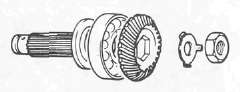
Middle Gear Service
Middle Gear ServiceMIDDLE GEAR SERVICE

1 Spring retainers
2 Spring seat
3 Damper cams
4 Midde drive gear shim
5 Bearing
6 Bearing retainer
7 Middle drive shaft
8 Middle driven shaft
9 Shim
10 O-ring
11 Bearing housing
12 Oil seal (35 x 5 0x6)
Gear Lash Measurement and Adjustment
Gear Lash Measurement and AdjustmentGEAR LASH MEASUREMENT
NOTE:
The middle gear lash can be checked only when the gears are installed in the crankcase.

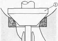
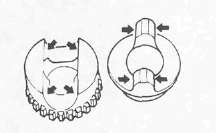
1. Attach:
• Middle Drive Pinion Holder (90890-04051) 1 .
NOTE:
Before installing the tool, loosen the holder bolt all the way out and after installation tighten this bolt as tight as necessary (finger tight is generally sufficient).

2. Attach a dial gauge against the middle drive flange as shown
3. Measure middle gear lash by rotating the flange gently back and forth. Follow Gear Lash Adjustment procedure if lash is not within specified limits.
Middle Gear Lash: 0.1 - 0.2 mm (0.004 - 0.008 in)
NOTE: Check this engagement at 4 points. If the gear lash exceeds the specified limit and adjustment is necessary, the engine or swing arm should be removed from the motorcycle.
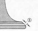
GEAR LASH ADJUSTMENT

1. Install the driven gear housing assembly into the crankcase leaving about a 2 mm (0.080 in) gap 1 between the housing and crankcase and install the two bolts 2 to the bearing housing 180° opposite to each other.
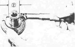
2. Attach:
• Middle Drive Pinion Holder (90890-04051)1 .
• Dial gauge
3. Slowly tighten the bolts alternately until the dial gauge lash measurement reaches 0.2 mm (0.008 in).

4. Measure the clearance between the bearing housing and the crankcase. This clearance is the shim size required.

5. Install the proper sized shim(s) 1
6. Tighten the bearing housing.
Bearing Housing: 25 Nm (2.5 mkg, 18 ft-lb)
7. Recheck the middle gear lash. Readjust if necessary.
Middle Gear Removal and Disassembly
Middle Gear Removal and DisassemblyREMOVAL
Middle Drive Gear
NOTE:
Middle drive gear and its shims can be removed without separating the engine.
1. Remove the clutch cover. Refer to "ENGINE DISASSEMBLY."
2. Strike the middle drive shaft out 1

3. Remove
• Middle drive shaft 1
•Shims 2
DISASSEMBLY Middle Drive Gear

1. Remove:
• Spring retainer. Use Damper Compressor (90890-04090) 1 with hydraulic press 2 .
• Spring seat 3
• Spring 4
• Damper cam 5

6 Middle drive shaft nut
7 Bearing
8 Shim
9 Middle drive shaft
NOTE:
Perform following steps only if middle-drive-shaft bearing or gear must be replaced.
2. Secure middle drive shaft in a vise.
3. Flatten the locking collar of the nut with a center punch.
4. Remove:
• Middle drive shaft nut
• Bearing
• Middle drive pinion
Middle Driven Gear

1. Support the drive flange in a vise securely.
2. Remove:
• Flange holding nut
• Flange 1
Middle Gear Inspection and Reassembly
Middle Gear Inspection and ReassemblyINSPECTION
1. Check
• teeth of middle gear for discoloration/Pitting/Wear. If necessary, replace all middle gears as a set.
• Damper cam surfaces for wear/Unsmooth action. Replace if necessary.
2. Check bearing movement. Rotate the race by finger and replace if rough.
ASSEMBLY AND ADJUSTMENT
1. Select proper middle-drive-gear shim.
NOTE:
Select proper middle-drive-gear shim whenever crankcase and/or middle gears are replaced.


Shim thickness calculation:
Calculate shim thickness using formula below:
Shim thickness (A) = c - a - b
a = 43 plus or minus the number printed on end of middle drive shaft.
b = a bearing thickness. (Considered constant)
c = 60 plus the number found on the upper crankcase half near the main bearing selection numbers:
For example:
If middle drive shaft is marked "+03" and crankcase is tamped "45".
a= 43 + 0.03 = 43.03 mm
c= 63 + 0.45 = 60.45 mm
b= 16.94 mm (Constant)
A = 60.45 - 43.03 - 16 .94 = 0.48 Calculated shim thickness is 0.48 mm.
Available shim thickness: 0.15 mm, 0.30 mm, 0.40 mm, 0.50 mm
Because shim can only be selected in 0.05 mm increments, use following chart to round off the hundredths digit of calculated thickness, and select appropriate shim.
|
Hundredths digit |
Rounded value |
|
0,1,2 |
0 |
|
3,4,5,6 |
5 |
|
7,8,9 |
10 |
In above example, calculated shim thickness is 0.48 mm. The chart instructs you, however, to round off the 8 to 10. Thus you should use two 0.50 mm shims.
2. Install:
• Middle drive shaft bearing.
• Middle drive pinion
• Lock washer (New)
• Nut
3. Tighten the nut
4. Bend lock washer of nut into middle drive shaft slot using a center punch.

5. Assemble:
• Damper cam 1
• Spring 2
• Spring seat 3
• Spring retainer
Use a Press and Damper Compressor (90890-04090)4.

NOTE:
Install the driven damper cam onto the drive pinion shaft with the cam lobes positioned 90° from the row of shaft oil holes 1. Positioning tolerance is ±1 spline (15°) from the 90° position.
Middle Drive Shaft Nut: 110 Nm (11 m-kg, 8 0 ft-lb)
6. Install:
• Bearing housing (onto the drive pinion shaft)
• Flange
• O-ring (New) (onto the drive pinion shaft)

7. Tighten:
• Flange holding nut
Flange Holding Nut: 90 Nm (9.0 m-kg, 65 ft-lb) LOCTITE®

8. Lock the thread on the holding nut with a center punch.
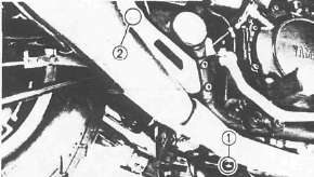
Remounting the Engine
Remounting the Engine
1. Refer to engine removal. Reverse those removal steps that apply.
2. Tighten engine mounting bolts
Engine Mounting Bolt: Front 1: 42 Nm (4.2 m-kg, 30 ft-lb)
Rear 2 : 90 Nm (9.0 m-kg, 65 ft-lb)
Down Tube 3 , Bracket 4 : 33 Nm (3.3 m-kg, 24 ft-lb)
3. Connect:
• Pickup coil lead
• Generator lead
• Neutral switch lead
• Oil level switch lead
• Starter motor lead
• Crankcase ventilation hose
• Battery leads
NOTE:
•See CHAPTER 8 "Cable Routing" for proper cable, lead, and hose routing.
• Connect the battery positive lead first.
• Make sure that the cables are not twisted.
• Be careful not to pinch the leads.
4. Install the Carburetors. Note: see Carburetor section for further details.
5. Connect:
• Throttle cable
• Starter cable
6. Tighten the air cleaner case mounting bolts
Air Cleaner Case: 10Nm{1.0m-kg, 7.2ft-lb)
7. Install:
• Fuel tank
• Seat
8. Add:
• Engine oil
Engine Oil: 3.5 L (3.1 Imp qt, 3.7 US qt)
• Coolant
Recommended Coolant: High Quality Ethylene Glycol Antifreeze Containing Anti-corrosion for Aluminum Engine Inhibitors Coolant and Water.
Mixed Ratio: 50%/50%
Total amount: 2.4 L (2.11 Imp qt, 2.54 US qt) .
Reservoir Tank Capacity: 0.49 L (0.43 Imp qt, 0.52 US qt)
From "LOW" to "FULL" Level: 0.14 L (0.12 Imp qt, 0.15 US qt)