COOLING SYSTEM

3 Main switch
4 Fuse "FAN" (10A)
5 Thermo switch
6 Fan motor
18 Temperature meter
19 Thermo unit
35 Fuse "SIGNAL" (15A)
48 Battery
49 Fuse "MAIN" (30A)

TROUBLESHOOTING CHART (1)
|
TEMPERATURE GAUGE DOES NOT OPERATE. |
||
|
▼ |
||
|
Remove the fuel tank. |
||
|
▼ |
||
|
Turn the main switch "ON". |
||
|
▼ |
||
|
Disconnect the thermo unit connector. Check the battery voltage (12V) on Green/Red lead from the wire harness, |
No |
Check for an open or poor connection between the fuse "SIGNAL" and thermo unit connector. |
|
▼ Yes |
||
|
Disconnect the thermo unit connector. Connect the Green/Red lead from the wire harness to "ground" on the frame; use a jumper lead 1 . |
No ► |
Replace the temperature gauge. |
|
▼ |
|
|
|
The temperature gauge needle will swing from "C" to "H". |
||
|
▼ Yes |
||
|
Replace the thermo unit. |
TROUBLESHOOTING CHART (2)
|
ELECTRIC FAN MOTOR DOES NOT OPERATE. |
||
|
▼ |
||
|
Disconnect the thermo switch 1 lead.
|
||
|
▼ |
||
| Check for the battery voltage (12V) on Brown lead from the wire harness. | No ► |
Check for an open or poor connection between the fuse "FAN" and thermo switch connector. |
| ▼ Yes | ||
|
Connect the Brown lead and Blue lead; use a jump lead 1 .
|
||
| ▼ | ||
| The fan motor operates. | No ► |
Replace the fan motor. |
| ▼ Yes | ||
| Replace the thermo switch. | ||
THERMO UNIT AND THERMOMETER
Operation
The thermo unit has less resistance at higher temperatures and thus allows more current to pass through. When more current flows to the coil in the temperature gauge; the armature to which the needle is attracted by the increased magnetic field. In this way, the needle indicates the temperature.
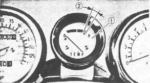
1 Temperature gauge
2 Red zone
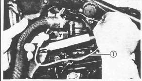
Thermo Unit Inspection

1. Remove:
• Thermo unit 1
CAUTION:
Handle the thermo unit with special care. Never subject it to strong shock or allow it to be dropped. Should it be dropped, it must be replaced.
2. Check the thermo unit operation
Thermo unit inspection steps:
• Immerse thermo-unit in water.
• Check continuity at indicated temperatures. Note temperatures while heating the water.

1 Temperature gauge
2 Thermo unit
3 Pocket tester
4 Water
|
Water Temperature |
50°C (122°F) |
100°C (212°F) |
120°C (248°F) |
|
Resistance |
156Ω |
28.4Ω |
17Ω |

3. Install the thermo unit 2
4. Tighten the thermo unit
Thermo Unit 2 : 15 Nm (1.5m-kg, 11 ft lb)
CAUTION:
After replacing the thermo unit, check the coolant level in the radiator and also check for any leakage.
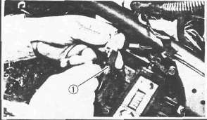
ELECTRIC FAN AND THERMO SWITCH
Operation
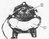
The electric fan will be switched ON or OFF according to the coolant temperature in the radiator.
1 Electric fan motor
NOTE:
The electric fan is controlled by the thermo switch when the main switch is "ON". Thus, under certain operating conditions, this fan may continue to run until the engine temperature has cooled down to about 98°C (208.4°F).

A THERMO SWITCH "ON"
B COOLANT TEMPERATURE
|
The following problems may require repair or replacement of components |
|
|
Component |
Condition |
|
Fan motor |
Unsmooth operation |
|
Fan motor bracket |
Cracks |
|
Securing bolts |
Looseness |
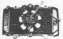
1 Fan
2 Electric fan motor
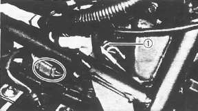
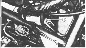
Thermo Switch Inspection
1. Remove the thermo switch 1
CAUTION:
Handle the thermo switch very carefully. Never subject it to strong shock or allow it to be dropped. Should it be dropped, it must be replaced.
2. Inspect the thermo switch operation
Thermo switch inspection steps:
• Immerse thermo switch in oil.
• Check continuity as indicated temperatures. Note temperatures while heating the oil.

1 Temperature gauge
2 Thermo switch
3 Pocket Tester
4 Oil
|
Test step |
Oil temperature |
Pocket Tester (Ω x 1) |
|
1 |
0- 98°C (32~208.4°F) |
Discontinuity |
|
2 |
More than 105°±3°C (more than 221.0 ±5.4°F) |
Continuity |
|
3* |
105 to 98°C (221.0- 208.4°F) |
Continuity |
|
4* |
less than 98°C (less than 208.4°F) |
Discontinuity |
Test 1 & 2: Heat-up tests
Test 3* & 4*: Cool-down tests
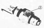
3. Install the thermo switch 2
Thermo Switch 2 : 23 Nm (2.3 m-kg, 27 ft-lb)
CAUTION:
After replacing ther thermo switch, check the coolant level in the radiator and also check for any leakage.
- Printer-friendly version
- Log in to post comments