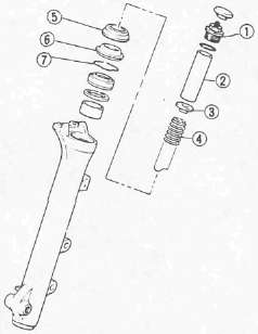
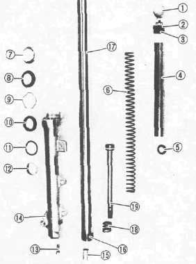
FRONT FORK

1 Cap bolt
2 O-ring
3 Spacer
4 Spring seat
5 Fork spring
6 Damper rod
7 Inner fork tube
8 Slide bushing
9 Taper spindle
10 Dust seal cover
11 Dust seal
12 Circlip
13 Fork seal
14 Washer
15 Guide bushing
16 Outer fork tube
17 Damper rod securing bolt
FORK OIL: Capacity (Each leg): 389 cm3 (13.7 Imp. oz, 13.2 US oz)
Type: YAMAHA FORK & SHOCK OIL 10Wt or equivalent fork oil
SPRING FREE LENGTH LIMIT: 505 mm (19.9 in)
AIR PRESSURE
Standard: 39.2 kPa (0.4 kq/cm\ 5.7 psi)
Maximum: 118 kPa (1.2 kg/cm2, 17 psi)
Minimum: Zero

REMOVAL AND DISASSEMBLY
Support the motorcycle securely so there is no danger of it falling over.

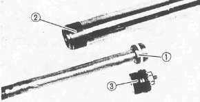
1. Remove the air valve cap 1
NOTE:
Keep the valve 2 open by pressing it for several seconds so that the air can be let out of the inner tube.
2. Loosen:
• Inner tube pinch bolt 3
• Cap bolt 4
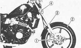
3. Remove:
• Brake caliper 1
• Front wheel 2
• Fork brace 3
4. Loosen:
• Lower front fork pinch bolts 4
CAUTION:
Support the fork before loosening the pinch bolts.
5. Remove:
• Front fork assembly (from the under bracket)
• Cap bolt 1
• Spacer 2
• Spring seat 3
• Fork spring 4
• Dust seal cover 5
• Dust seal 6
• Circlip 7
6. Fill the fork inner tube with fork oil. Stretch the inner tube before filling.
7. Install the Cap bolt 1
8. Remove oil seal from outer tube. Press the inner tube to facilitate removal.
CAUTION:
• If air enters the inner tube or it is compressed abruptly oil may spurt out or the coil seal may be ejected.
• Never touch the inner tube during a disassembly operation.
• Be sure to wrap the oil seal with a rag for safety.
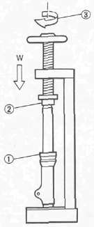
1 Wrap with rag
2 Socket wrench (suitable socket)
3 Turn slowly
9 Remove:
• Oil seal
• Washer
• Cap bolt
• Fork spring
10. Drain the oil from the fork.

11. Remove the damper rod securing bolt. Use T-handle (90890-01326) 1 and Damper Rod Holder (90890-01365) 2 to remove the damper rod. The holder can be fabricated by securing double nuts requireing a 19mm socket to a bolt or length of threaded rod. These will fit into the 19mm hex in the base of the fork and can then be held with a socket and long extension.

12. Remove:
• Damper rod
• Damper rod spring
• Inner fork tube
• Guide bushing (from outer tube)
• Slide bushing
• Taper spindle
1 Pull inner tube from outer tube.
INSPECTION
1. Inspect the inner fork tube. Replace if severe scratches, bends or a damaged oil lock valve are found.
Do not attempt to straighten a bent fork tube as this may dangerously weaken the tube,
2. Inspect the outer fork tube. Replace if bent or if fork seal seat is damaged.
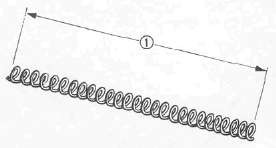
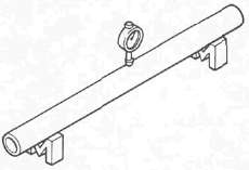
3. Measure the spring free length 1. Replace if less than limit.
Fork Spring Free Length Limit: 505 mm (19.9 in)
4. Inspect the damper rod. Replace seal and/or slide bushing if worn. Replace Cap bolt o-ring if damaged. Wash and blow out all passages.
ASSEMBLY
NOTE:
• Be sure all components are clean before assembly.
• Always install the new oil seal, bushings, and the dust seal. Do not reuse them.
1 Cap
2 O-ring
3 Cap bolt
4 Spacer
5 Spring seat
6 Fork spring
7 Dust seal cover
8) Dust seal
9 Circlip
10 Fork oil seal
11 Washer
12 Guide bushing
13 Damper rod securing bolt
14 Outer fork tube
15 Taper spindle
16 Slide bushing
17 Inner fork tube
18 Damper rod spring
19 Damper rod
1. Install:
• Damper rod spring
• Damper rod. Allow rod to slide slowly down the inner fork tube until it protrudes from the bottom.
• Taper spindle
• Inner fork tube
2. Install damper rod securing bolt. Hold damper rod with Damper Rod Holder (90890-01365) and T-handle (90890-01326).
Damper Rod Securing Bolt:
30 Nm (3.0 m-kg, 22 ft-lb) LOCTITE® Stud N'Bearing Mount (red)

3. Install the guide bushing 1 Press guide bushing into the outer fork tube with Fork Seal Driver (90890-01367) 2 and Adapter (90890-01372)3. A substitute can be fabricated from 1 1/2" ABS drain pipe.

4. Install:
• Washer 1
• New fork oil seal 2. Press fork oil seal into the outer fork tube with Fork Seal Driver (90890-01367) 3 and Adapter (90890-01372) 4.

5. Install:
• Circlip1
• Dust seal 2
• Dust seal cover 3
6. Fill:
• Front fork with fork oil.
Capacity: 389 cm3 (13.7 Imp. oz, 13.2 US oz)
Type: Yamaha Fork & Shock Oil 10Wt or equivalent fork oil
WARNING:
Ensure each fork is filled with the same amount of oil or bike may develop a deadly wobble at speed.
7. Install:
• Fork spring
• Spring seat
• Spacer
• Cap bolt (into the inner fork)
8. Install the front fork assembly into the under bracket.
9. Tighten:
• Lower front fork pinch bolts.
• Cap bolt
Cap Bolt: 23Nm(2.3m-kg, 17ft-lb)
10. Loosen Lower front fork pinch bolts
11. Install front fork into the steering crown.
NOTE:
Be sure the inner fork tube end is flush with the top of the steering crown.

12. Tighten:
• Front fork pinch bolt (Upper) 1
• Front fork pinch bolts (Lower) 2
Upper Pinch Bolt: 20 Nm (2.0 m-kg, 14 ft-lb)
Lower Pinch Bolts: 23Nm(2.3m-kg, 17ft-lb)
13. Continue assembly by reversing of Removal and Disassembly sequence. Install and torque tighten each component as specified.
Disc Brake Caliper: 35 Nm (3.5 m-kg, 25 ft-lb)
Front Wheel Axle: 105 Nm (10.5 m-kg, 75 ft-lb)
Wheel Axle Pinch Bolt: 20Nm(2.0m-kg, 14 ft-lb)

14. Fill front fork with air
Standard Air Pressure: 39.2 kPa (0.4 kg/cm2, 5.7 psi)
15. Install air valve cap
- Printer-friendly version
- Log in to post comments