LOWER CRANKCASE

1 Drive axle assembly
2 5 th wheel gear
3 O-ring
4 Housing
5 Shift cam
6 Shift cam locating pin
7 Shift fork 3
8 Shift fork 2
9 Shift fork 1
10 Shift fork guide bar
11 Circlip
12 Dowel pin
13 Blind plug
14 Middle drive gear assembly

1. Install:
• Drive axle assembly 1
• 5th wheel gear 2
• new O-ring 3 onto the housing 4
• Drive axle bearing housing 4
Drive Axle Bearing Housing: 12 Nm (1.2 m kg, 8 .7 ft-lb)

2. Install:
• Shift cam 1
• Shift cam locating pin 2
• Stopper plate 3
• Bolt
• Neutral switch 4
Shift Cam Locating Pin: 8 Nm (0.8 m-kg, 5 .8 ft-lb)
Neutral Switch: 20 Nm (2.0 m-kg, 14 ft-lb)
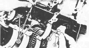
3. Install:
•Shift forks 2
•Guide bar 1
NOTE: • All
shift fork numbers should face the left side and be in sequence (1, 2 ,
3 ), starting from the left.
• The guide bar groove 3 should face the right side.
4. Place the shift cam and transmission gears in NEUTRAL position.
CAUTION:
Be sure the gear shifts correctly while hand-turning the shift cam.
5. Clean the crankcase counterbore where the main bearing is fitted.
6. Install the crankshaft bearings See inspection for crankshaft bearing selection.
CRANKSHAFT
1. Clean:
• Crankshaft
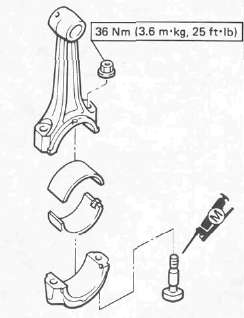
• Connecting rods
2. Install the connecting rod bearings into connecting rod and cap.
3. Lubricate the connecting rod bolt threads with Molybdenum Disulfide Grease
4. Apply engine oil to the crankshaft pins.
5. Install:
• Connecting rods
• Rod caps

NOTE:
• Be sure the letter on both components align to form a perfect character.
• The stamped "Y" mark on the connecting rods 1 should face towards the left side of the crankcase.
- Printer-friendly version
- Log in to post comments