SIGNAL SYSTEM

3 Main switch
15 Tachometer
16 "FUEL" warning light
17 Fuel sender
20 Horn
21 "HORN" switch
22 Flasher relay (Relay assembly)
23 Flasher switch
24 Reed switch
25 Flasher light (Front, Right)
26 Flasher light (Rear, Right)
27 "TURN" indicator light (Right)
28 "TURN" indicator light (Left)
29 Flasher light (Rear, Left)
30 Flasher light (Front, Left)
31 "OIL LEVEL" indicator light
32 Oil level switch
33 "NEUTRAL" indicator light
34 Neutral switch
35 Fuse "SIGNAL" (15A)
36 Brake switch
37 Tail/Brake light
44 "START" switch
48 Battery
49 Fuse "MAIN" (30A)
50 Diode assembly

FLASHER LIGHT Troubleshooting
|
Flasher light and indicator light inoperative. |
||
| ▼ | ||
|
Check bulb. |
Faulty ► |
Replace.
|
|
▼OK |
||
|
Measure voltage at flasher switch (Br/W wire and Y/R wire). |
12V |
Check flasher switch, replace if necessary.
|
|
▼ No voltage |
||
|
Check flasher relay, main fuse, signal fuse and battery. |
Faulty and/or battery discharged . ► |
Replace faulty parts and/or charge battery.
|
|
▼ OK |
||
|
Check reed switch. |
Defect ► |
Replace.
|
|
▼ OK |
||
|
Replace flasher relay (Relay assembly). |
||
FLASHER RELAY (Relay Assembly)
NOTE
Flasher relay and self cancelling unit are included with relay assembly.
The flasher relay turns off the flashers. Generally the signal will cancel after either 10 seconds of operation or after the motorcycle has traveled 150 meters (490 feet), whichever is greater. At low speed, the cancelling is a function of distance; at high speeds, it's a function of both time and distance.
The flasher switch has three positions: L (left), OFF, and R (right). The switch lever will return to the "OFF" position after being pushed to L or R, but the signal will function. By pushing the lever in, the signal may be cancelled manually.
REED SWITCH
1. Remove:
• Headlight unit
• Headlight body
2. Disconnect the coupler
3. Connect pocket tester
4. Lift the front wheel and rotate the wheel by hand.
5. Measure reed switch resistance
Reed Switch Resistance: About 7 Then return back OΩ or ∞Ω when wheel is stopped
OIL LEVEL INDICATOR LIGHT
1. Troubleshooting
|
Oil level indicator light inoperative |
|||
|
Check bulb |
Faulty |
Replace |
|
|
▼ OK |
|
|
|
|
Measure voltage at oil level switch (Red/Black) |
No voltage |
Check diode, signal fuse, main switch, main fuse, and battery. Replace faulty parts. |
|
|
▼ 12V |
|
|
|
|
Check oil level switch, replace if necessary. |
|
||

1 Red/Black lead
2 Ground
FUEL WARNING INDICATOR LIGHT
1. Troubleshooting

|
Fuel warning indicator light inoperative |
|||
|
▼ |
|
||
|
Check bulb |
Faulty |
Replace |
|
|
▼ OK |
|
|
|
|
Measure voltage at fuel sender unit (Green). |
No voltage |
Check signal fuse, main switch, main fuse, and battery. Replace faulty parts. |
|
|
▼ 12V |
|
||
|
|
|||
|
Check fuel sender, replace if necessary. |
|
||

1 Green
2 Black
FUEL SENDER UNIT
1. Remove seat
2. Fill the fuel tank (with gasoline)

3. Measure the fuel sender unit resistance.
Fuel Sender Unit Resistance: 1.1 ±0.2kΩ @ 20°C (68°F)
NEUTRAL INDICATOR LIGHT
1. Troubleshooting
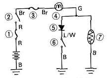
1 Main fuse
2 Main switch
3 Signal fuse
4 Fuel warning indicator Igiht
5 Diode
6 Starter switch
7 Fuel sender
|
Neutral indicator light inoperative |
||
|
|
||
|
Check bulb |
Faulty |
Replace
|
|
▼ OK |
||
|
Measure voltage at neutral switch (Sb wire) |
No voltage |
Check signal fuse, main switch, main fuse, and battery, Replace faulty parts. |
|
▼ 12V |
|
|
|
|
||
|
Check neutral switch. Replace if necessary. |
|
|

1 Blue lead
2 Ground
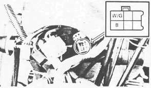
HORN
1. Check:
|
Check for: |
Horn inoperative |
|
12V on brown lead to horn |
|
|
Good ground (horn/pink wire) when horn button is pressed |
|
|
Faulty |
Defective components — Replace.
NOTE:
There are individual fuses for various circuits (See Complete Circuit Diagram)

2. Measure the horn resistance
Horn Resistance: 1.05Ω ± 10%
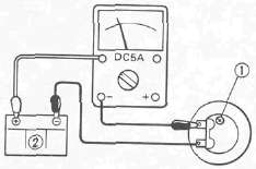
3. Adjust the volume. Turn the adjuster 1 in and out so that the volume is maximum at the maximum amperage.
2 Battery (12V)
|
Tester's lead wire |
Maximum Amperage |
Tester's range |
|
|
Red lead |
Black lead |
||
|
Battery (+) lead |
Horn lead and Battery (-) lead |
2.0A |
DC5A |
BRAKE LIGHT
|
Check for: |
Brake light inoperative |
|
Defective bulb |
|
|
12V on yellow lead to brake light |
|
|
12V on brown lead to each brake light switch (Front and rear brake switch) |
- Printer-friendly version
- Log in to post comments