1. Remove
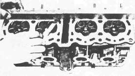
• Lifters 1
• Valve pads 2
NOTE:
Identify each lifter and pad position very carefully so that it can be reinstalled in its original place.

2. Measure the warpage using a precision straight edge or surface plate and feeler gauges. Resurface if warpage exceeds allowable limit.
Cylinder Head Warpage: Less than 0.03 mm (0.0012 in)

3. Remove the camshaft case 1

4. Remove:
• Camshaft case gasket 1
• Dowels 2
• Cylinder head nuts
• Plain washers

5. Attach:
• Valve Spring Compressor (90890-04019) 1
• Attachment (90890-04108) 2

6. Remove:
• Valve retainers 1
• Valve spring seat 2
• Valve spring 3
• Oil seal 4
• Valve spring seat 5
• Valve 6
NOTE:
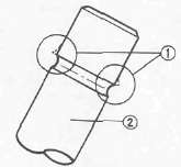
Deburr any deformed valve stem end. Use an oil stone to smooth the stem end.

1 Deburr 2 Valve stem
7. Eliminate:
• Carbon deposit (from combustion chamber) Use rounded scraper.
NOTE:
Do not use a sharp instrument and avoid damaging or scratching:
• Spark plug threads
• Valve seat
• Aluminum
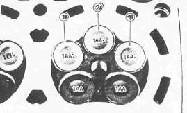
8. Install:
• Valves

NOTE:
Be sure the "1AA : " mark 1 valves are for intake left and right and "1AA •" mark 2 for intake center.
9. Install the valve springs

NOTE:
• All valve springs must be installed with the larger pitch 1 upward as shown.
• Be sure the "Blue" spring is for intake and "Red" for exhaust.
2 Smaller pitch

10. Install:
• Dowels 1
• Camshaft case gasket 2
NOTE:
Be sure the "UP" mark face to upward.
• Plain washers 3
• Cylinder head nuts 4

11. Install the camshaft case 1. Torque the camshaft case bolts to 10 Nm (1.0m-kg, 7.2ft-ft)
- Printer-friendly version
- Log in to post comments
