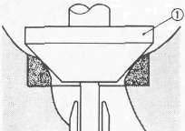
1. Measure the valve stem clearance


Use a bore gauge 3 to determine the valve guide inside diameter.
Valve Guide Inside Diameter Limit: 5.05 mm (0.199 in)
2. Measure the valve stem diameter with a micrometer. Replace guide if clearance exceeds specification.
Valve stem clearance = Valve guide inside diameter 1 minus Valve stem diameter 2
Valve Stem Clearance Limit:
Intake 0.08 mm (0.003 in)
Exhaust 0,10 mm (0.004 in)
3. Examine the valve face for pitting or wear and regrind as necessary. Measure the valve face as indicated below and replace if valve cannot be brought back to specification.

Minimum Thickness (Service limit) 1 : 0.7 mm (0.028 in)
Beveled 2 : 0.35 mm (0.014 in)
Minimum Length (Service limit) 3 :14.5 mm (0.6 in)

4. Check:
• Valve stem end Mushroom shape and/or diameter. Replace if larger than rest or stem.
• Runout. Replace if it exceeds specification.
Maximum Valve Stem Runout: 0.01 mm (0.0004 in)
5. Inspect the valve guide for signs of wear and/or oil leakage. Replace if excessive.
NOTE:
Heat the
cylinder head in an oven to 100°C (212°F) to ease valve guide removal
and reinstallation and to maintain correct interference fit.

Valve Guide Replacement
1. Remove the valve guide. Use Valve Guide remover 1 (90890-04097)
NOTE
• Always replace valve guide if valve is replaced.
• Always replace oil seal if valve is removed.

2. Install the new valve guide with Valve Guide Installer 1 (90890-04098) and Valve Guide Remover (90890-04097).

3. Bore valve guide 1 to obtain proper valve stem clearance. Use 5 .0 mm (0.20 in) Reamer 2 (YM-04099).
Valve Seat
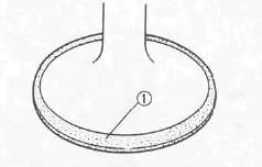
1. Inspect the valve seat for pitting/wear. Cut new faces as required.

2. Measure the valve seat width 1. Follow the next steps if out of specification.
|
|
Standard width |
Wear limit |
|
Valve seat width |
1.0 ± 0.1 mm (0.040 ± 0.004 in) |
1.8 mm (0.070 in) |
3. Apply:
• Mechanic's bluing dye (Dykem) (to valve and seat)
• Fine grinding compound (Small amount) (to valve face surface)
4. Position the valve into the cylinder head.
CAUTION:
Do not allow any compound to contact the valve stem or guide. Flush thoroughly as required.

5. Spin it rapidly back and forth, then lift valve and clean off all grinding compound.
6. Inspect the valve seat surface. Wherever valve seat and valve face made contact, blueing will have been removed.

7. Measure:
• Valve seat width 1
• Contacting position 2
Recut if out of specification.
Width 1 : 1.0 ± 0.1 mm (0.040 ± 0.004 in)
Position 2 : 0.3 mm (0.012 in)
8. Cut valve seat.
NOTE:
Cut valve seat using valve seat cutter 1 if valve seat width exceeds limit or if valve seat is pitted or worn.
CAUTION:
When twisting cutter, keep an even downward pressure to prevent chatter marks.
Valve seat recutting steps are necessary if:
• Valve seat is uniform around perimeter of valve face but too wide or too narrow or not desired position on valve face.

|
Cut valve seat as follows: |
|
|
Section A |
20° Cutter |
|
Section B |
45° Cutter |
|
Section C |
60° Cutter |

|
• Valve face indicates that valve seat is in desired position 1 but too wide |
||
|
Valve seat cutter set |
Desired result |
|
|
Use |
20° Cutter 6 0° Cutter |
to reduce valve seat width. |

|
• Valve seat is desired position 2 but too narrow |
||
|
Valve seat cutter set |
Desired result |
|
|
Use |
45° Cutter |
to achieve a uniform valve seat width (Standard specifications). |
|
• Valve seat is too narrow and touching the valve margin 3. |
||
|
Valve seat cutter set |
Desired result |
|
|
Use |
20° Cutter, first 45 ° Cutter |
to obtain correct seat width. |

|
• Valve seat is too narrow and touching the bottom edge of the valve face 4. |
||
|
Valve seat cutter set |
Desired result |
|
|
Use |
60° Cutter, first 45 ° Cutter |
to obtain correct seat width. |
NOTE:
Lap valve/valve seat assembly if:
•Valve face/valve seat are used or severely worn.
•Valve and valve guide has been replaced.
•Valve seat has been cut.
Valve/Valve Seat Assembly Lapping
1. Apply coarse lapping compound (Small amount!) to valve face.
2. Position the valve (in cylinder head)

3. Rotate the valve. Turn until valve and valve seat are evenly polished, then clean off compound.
4. Repeat above steps with fine compound and continue lapping until valve face shows a completely smooth surface uniformly.
5. Eliminate all compound from valve face.
6. Apply mechanic's bluing dye (Dykem) 1 to valve face and seat.
7. Rotate the valve. Valve must make full seat contact indicated by grey surface all around valve face where bluing was removed.
8. Apply solvent into each intake and exhaust port. If solvent leaks past valve seat, relap until seal is complete.
NOTE:
Pour solvent into intake and exhaust ports only after completion of all valve work and assembly of head parts.
Re-lapping steps:
• Disassemble head parts.
• Repeat lapping steps using fine lapping compound.
• Clean all parts thoroughly.
• Reassemble and check for leakage again using solvent.
• Repeat steps as often as necessary to effect a satisfactory seal.

Valve Spring Measurement
Measure the valve spring free length. Replace if out of specification.
Valve Spring Free Length (Limit):
|
lntake Spring |
Exhaust Spring |
|
|
37.76 mm (1.487 in) |
37.96 mm (1.495 in) |
|

2. Measure:
• Installed length 1
• Valve spring installed force 2
Replace if out of specification.
Valve Spring Installed Force:
|
Intake Spring |
Exhaust Spring |
||
|
1 |
2 |
1 |
2 |
|
35.0 mm |
7.3-8.7 kg |
35.0 mm |
11.0-13.0 kg |
- Printer-friendly version
- Log in to post comments