Upper Crankcase
Upper CrankcaseUPPER CRANKCASE

1 Crankshaft bearing
2 Drive chain guide
3 Starter idle gear
4 A.C.G. drive chain
5 Oil seal
6 Starter clutch assembly
7 Main axle assembly
8 A.C.G. shaft
9 O-ring
10 Oil spray nozzle
11 Housing
12 Cam chain guide
|
CONNECTING ROD BEARING SELECTION: |
|
|
CALCULATED NO. |
COLOR CODE |
|
1 |
BLUE |
|
2 |
BLACK |
|
3 |
BROWN |
|
4 |
GREEN |

1. Install:
• Crankshaft bearings 1
• Drive chain guide 2
• Starter idle gear 3
Drive Chain Guide: 8 Nm (0.8 m-kg, 5.8 ft-lb)
Starter Idle Gear: 8 Nm (0.8 m-kg, 5.8 ft-lb)
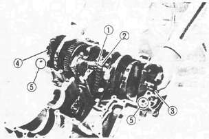
2. Apply engine oil to the bearings.
3. Place the cam chain 1 , drive chain 2 , and oil seal 3 onto the crankshaft.
4. Install the crankshaft (onto the upper crankcase)
NOTE:
• Insert the oil seal flange completely into the crankcase positioning groove.
•Be careful not to damage the oil seal duringinstallation.
• Blind plug 4
• Dowel pins 5
5. Place the drive chain on the starter clutch assembly.
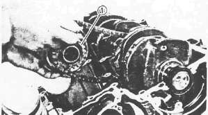
6. Install
• Starter clutch assembly 1 onto the upper crankcase
• A.C.G. shaft
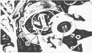
7. Install:
• Oil spray nozzle 1 with new O-ring 2
• Housing with new oil seal 3
NOTE:
Lightly apply grease to the oil seal lips.
Housing Bolt: 10 Nm (1.0 m-kg, 7.2 ft-lb) LOCTITE®

8. Install:
• O-ring (New) 1
• Dowel pins 2
• Half clips 3
• Main axle assembly 4
• Bearing 5
• Middle drive shaft assembly 6
9. Position the bearing pin (left bearing) as shown 7.
CRANKCASE ASSEMBLY

1. Attach a length of wire to the cam chain.
2. Apply Yamaha bond No. 1215 (908 8 5505).
NOTE:
DO NOT ALLOW any sealant to come in contact with the oil galley O-ring, or crankshaft bearings. Do not apply sealant to within 2-3 mm (0.08-0.12 in) of the bearings.
3. Install the lower crankcase onto the upper crankcase.

• Be sure the shift fork (No. 1 ) 1 engages the groove 2 in the 2nd pinion gear on the main axle.
• Insert the oil seal and blind seal flanges completely into the crankcase positioning grooves.
• Be careful not to damage the seals during installation.
4. Install:
• Bolts
• Washers
• Clamps
• Battery negative lead
5. Tighten:
• Crankcase bolts
Crankcase:
6 mm bolt: 12 Nm (1.2m-kg, 8.7ft-lb)
8 mm bolt: 24 Nm(2.4m-kg, 17 ft-lb)
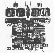
NOTE:
The embossed numbers in the crankcase designate the crankcase tightening sequence.

LOWER CRANKCASE
UPPER CRANKCASE