
1. Air valve
2. Cap bolt
3. Spring seat
4. Dust seal
5. O-ring
6. Circlip
7. Oil seal
8. Guide bushing
Front fork disassembly
Warning:
Securely support the motorcycle so it won't fall over when the front wheel and fork legs are removed.
1. Remove the cap from the fork air valve and depress the valves until the air pressure escapes completely from both fork legs.
2. Disconnect the speedometer cable from the speedometer drive unit.
3. Remove the brake calipers from the fork legs.
4. Remove the front wheel.
5. Remove the front fender.
6. Loosen the fork pinch bolts in the handle crown and underbracket.
7. Remove the fork assembly from the handle crown.
8. Remove the cap bolt, and remove the spring seat and fork spring..
NOTE:
Perform the fork leg disassembly and reassembly procedures on one fork leg at a time.
NOTE:
Do not drain the fork oil.
9. Remove the dust seal with a thin screwdriver. Take care not to scratch the inner fork tube. Discard the dust seal.
10. Remove the oil seal retaining clip.
11. Set the inner tube with approximately 50 mm (2 in) travel at the end and completely fill with fork oil.
Front fork oil: Yamaha Fork Oil 10wtor SAE 10W30 type SE motor oil
12. Reinstall and tighten the cap bolt assembly.
13. Slightly depress trie inner fork tube into the outer fork tube. Depress the air valve until the air pressure excapes completely from the fork.
CAUTION:
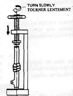
When using a press, protect the adjusting knob with a hood (socket or similar object) that can cover the adjusting knob whilst resting on the head of the cap-bolt assembly.
14. Using a press, slowly press the inner tube into the outer fork tube until the oil seal comes out or until oil leaks from the outer portion of the oil seal, remove the oil seal.
CAUTION:
If the inner tube is abruptly contracted or if air remains in the inner fork tube, oil may spurt out or the oil seal may spring out. Wrap a rag arround the end of the outer fork tube so oil will not spill all over the shop.
15. Remove the cap-bolt assembly. Place an open container under the fork, turn the fork upside down and drain the oil.
16. Inspect the O-ring on the cap-bolt, and replace the O-ring if it is damaged.
17. Remove the damper rod bolt from the bottom of the fork leg. (Using special tool)
18. Hold one hand over the top of the fork leg, and turn the leg upside down so the damping rod and rebound spring slide down and out of the fork leg; take care not to let the damper rod fall to the ground, as it may be damaged,
19. Holding the fork horizontally, clamp the axle-mounting boss of the outer fork tube securely in a soft jawed vise.
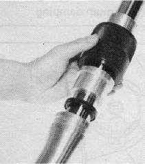
20. Slowly push the inner fork tube into the outer fork tube, and then pull the fork back quickly until it tops out. The guide bushing will be dislodged from the outer fork tube after doing this several times.
CAUTION:
Avoid bottoming the inner fork tube in the outer fork tube; the taper spindle could be damaged.
21. Remove all components of the oil lock valve assembly and inspect them; replace the assembly if there are any damaged components.
22. Clean all components of the fork leg and inspect them; replace any worn or damaged components prior to reassembly.
B. Inspection
1. Examine fork inner tube for scratches and straightness. If the tube is scratched severely or bent, it should be replaced.
Do not attempt to straighten a fork tube, since this may weaken the part dangerously.
2. Check the seal outer seat. If leakage is from this area, replace the seal. If this does not cure the leakage, replace the outer tube.
3. Check the outer tube for dents. If any dent causes the inner tube to "hang up" during operation, the outer tube should be replaced.
4. Check the free length of the springs.
Fork spring free length: 460.5 mm (18.13 in)
5. Check the "O-ring" on the cap bolt. If damaged, replace the "O-ring".
Front fork reassembly
1. Install the rebound spring on the damper rod.
2. Install the damper rod in the inner fork tube, and allow it to slide slowly down the tube until it protrudes from the bottom.
3. Place the taper spindle over the end of the damper rod, and insert the inner fork tube into the outer fork tube.
4. Apply a thread-locking compound such as Loctite® to the threads of the cylinder securing bolt, install the bolt in the damper rod, and torque it to specification. (Using special tool 90890-04084.)
Tightening torque: 20 Nm (2.0 m-kg, 14 ft-lb)
5. Install the guide bushing in the special 36 mm (1.4 in) fork tool (TLM-11080-10-00 or YM-08010). Use the tool to align the bushing in the top of the slider.

1. Guide bushing

6. Remove the large part of the fork tool, place the small part (TLM-11080-10-01 or YM-08010-1) on the guide bushing, and use the large part of the tool to drive in the bushing.
7. Oil and install a new oil seal in the top of the slider with the special tool. Making sure the beveled edge faces upward.
8. Install the retaining clip, and gently tap the dust seal into place with the special tool.
9. Pour the specified amount of the recommended fork oil into the inner fork tube.
Fork oil capacity: 257 cm3, (9.0 Imp oz, 8.7 US oz)
Recommended oil: Yamaha Fork Oil 10wt or SAE 10W30 type SE motor oil
10. Place the fork spring, spring seat, and spacer in the inner fork tube.
NOTE:
When installing the fork springs, the greater pitch should be at the bottom. The main fork spring has a small coil diameter at the bottom.

1. Top
2. Smaller pitch
11. Install the cap bolt assembly and tighten to specification.
Tightening torque: Cap bolt 30 Nm (3.0 m-kg, 22 ft-lb)
12. Slide the fork into the underbracket.
13. Push the fork assembly into the handle crown.
14. Torque the pinch bolts in the handle crown and underbracket.
Tightening torque: 20 Nm (2.0 m-kg, 14 ft-lb)
15. Install the cap onto the cap bolt. For the procedure, refer to "Front fork oil change".
16. Install the proper amount of air pressure in the fork legs. Take care not to exceed the maximum allowable air pressure.
Maximum fork air pressure: 118 kPa (2.5 kg/cm2, 17 psi)
17. Install the air valve caps.
WARNING:
Make sure no oil has contacted any disc brake components; oil will cause diminished braking capacity and damage the rubber components of the brake assembly. Make sure all oil is removed from the brake and actuating piston assemblies before they are reassembled and the motorcycle is operated.
18. Install the front fender, handlebar front wheel, and brake calipers.
19. Connect the speedometer cable to the drive unit, and check the operation of the motorcycle.
- Printer-friendly version
- Log in to post comments