3. Main switch
4. Main fuse (20 amp)
5. Battery (12V 14 AH)
6. Starter motor
7. Starter relay
8. Starter switch
9. Ignition fuse (10 amp)
10. Engine Stop switch
11. Starting circuit cut-off relay
12. Clutch switch
13. Sidestand relay
14. Sidestand switch
23 Neutral switch
B. Starting circuit operation
The starting circuit on this model consists of the starter motor, starter relay, and the starting/Circuit cut-off relay. If the engine stop switch and the main switch are both on, the starter motor can operate only if:
a. The transmission is in neutral (the
or if
b. The clutch lever is pulled to the handlebar (the clutch switch is on) and the sidestand is up (the sidestand switch is on.)
The starting-circuit cut-off relay prevents the starter from operating when neither of these conditions has been met. In this instance, the starting-circuit cut-off relay is off so current cannot reach the starter motor.
When one or both of the above conditions have been met, however, the starting-circuit cut-off relay is on, and the engine can be started by pressing the starter switch.

 When the transmission ii in neutral.
 When the clutch lever on the handlebar is pulled and the side stand is up.
1. Main fuse
2. To main switch
3. To computer monitor
4. From sidestand relay
5. From engine stop switch
6. From neutral light
7. Starting-circuit- cut-off relay
8. Neutral switch
9. Clutch switch
10. Sidestand switch
11. Starter switch
12. Starter motor
13. Starter relay
14. Battery
15. From side stand relay
C. Starting-circuit cut-off relay inspection
1. Open the seat, and remove the fuel tank.
2. Remove the starting-circuit cut-off relay from the frame, and disconnect the connector.

1. Starting circuit cut-off relay
3. Check the resistance of the relay coil windings with the pocket tester. If the resistance is not within specification, replace the relay

1. Starting-circuit cut-off relay
4. Check the relay function with a 12 volt battery and the pocket tester. Connect the leads as shown in the illustration. If the resistance readings do not equal those shown in the illustration, replace the relay.

1. When the battery is connected
2. When the battery is disconnected 3.12 volt battery
5. Check the diode in the starting circuit cut-off relay with the pocket tester as shown in the illustration. Replace the relay if the diode is damaged.
NOTE:
Only the Yamaha Pocket Tester will give a 9.5Ω reading when testing continuity. The particular characteristics of other testers will very the continuity test readings.
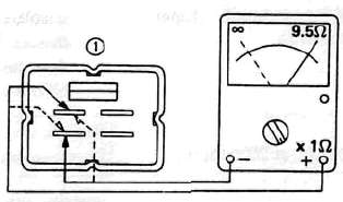
1. Starting-circuit cut-off relay
D. Starter Motor
1. Removal (see ENGINE OVERHAUL)
2. Inspection and repair
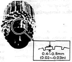
a. Check the outer surface of the commutator. If its surface is dirty, clean with # 600 grit sand paper.
b. The mica insulation between commutator segments should be 0.4 — 0.8 mm (0.02 "- 0.03 in) below the segment level. If not, scrape to proper limits with appropriately shaped tool. (A hack saw blade can be ground to fit.)
NOTE:
Mica insulation of commutator must be undercut to ensure proper operation of commutator.
c. The starter's armature coil should be checked with an ohm meter for insulation breakdown (shorting to each other or to ground) and for continuity. Reference figure is given below.
Coil resistance: Armature coil: 0.014H at 20°C (68°F)

Continuity check

Insulation check
d. Check the front and rear cover bearings for damage. If damaged, the starter assembly must be replaced.
e. Check brush length. Replace brush if at, or near, limits.
Minimum brush length: 8.5 mm (0.33 in)

f. Check brush spring pressure. Compare it with a new spring. Replace the old spring if it is weak.
E. Starter Relay Switch
1. Inspection
a. Disconnect starter cable at the relay.
b. Connect pocket tester leads to the relay terminals (ohms x 1 scale).
c. Turn ignition to "ON" position, engine stop switch to "RUN" and change lever to "NEUTRAL".
d. Push the starter button. The relay should click once and the scale should read zero if it does not read zero, the relay must be replaced.

1, Battery load wire l+l
2. Starter motor lead wire
e. If the relay does not click, check the wires from the starter button and from the battery (red/white, blue/white). Turn the ignition off. Use (ohms x 1) scale on tester. The resistance between these wires should be no more than 3.5 ohms. If there is more resistance, the relay should be replaced.

- Printer-friendly version
- Log in to post comments