E. Final Gear Reassembly
1. Install the new rear drive pinion roller bearing. Heat the bare bearing to 150°C (302°F) and use an appropriately adapter to install the roller bearing outer race. Install the inner race onto the drive pinion.
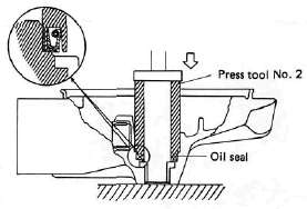
2. Using the press tool No. 2 (special tool) and a press, install the guide collet, new oil seal, and roller bearing into the main housing in that order.
NOTE:
The removed roller bearing can be used if undamaged however, Yamaha recommends replacement with a new one.

3. Final drive/ring gear positioning
NOTE:
When the following part(s) is replaced with new one(s), gear positioning is necessary:
a. Final gear case,
b. Ring gear bearing housing,
c. Bearing(s)

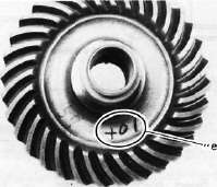
a. The shim thickness "A" necessary for the drive pinion gear positioning can be calculated from the information found on the final gear case and on the drive gear end.

1. Size number

To fined shim thickness "A" use the
formula:
A = a -b
Where:
a = a numeral (usually a decimal number) on the gear near the tooth and either added to or detracted from the nominal size "84".
b = a numeral on the gear case appearing as a whole figure (ie. 83.50).
Example:
1) If the pinion gear is marked "+01"....."a" is 84.01.
2) If the gear case is marked "83.50".
A = 84.01 - 83.50
A = 0.51
Then the necessary shim thickness is 0.51mm.
Shim sizes are supplied in the following thicknesses:
0.15 mm,
0.30 mm,
0.40 mm,
0.50 mm,
0.60 mm.
Because the shims can only be selected in 0.05 mm increments the following chart should be used when encountering last digits that are not 5 or zero (0):
|
Last digits |
Rounding |
|
0,1,2 |
0 |
|
3, 4, 5, 6, 7 |
5 |
|
8,9 |
10 |
b. The shim thickness "B" necessary for the ring gear positioning can be calculated from the information found on the final gear case, ring gear, and bearing.
To find shim, thickness "B" use the
formula:
B = c + d-(e + f)
Where:
c= a numeral on the gear case appearing as a whole figure (ie. 45.52)
d = a numeral (usually a decimal number) on the outside of the ring gear bearing housing and added to the nominal size "3".
e= a numeral (usually a decimal number) on the inside of the ring gear and; either added to or detracted from the nominal size "35.40".
f = a bearing thickness (considered constant)
Distance "f" = 13.00 mm
Example:
1) If the gear case is marked "45.52".
2) If the ring gear bearing housing is marked "35"....."d" is 3.35.
3) If the ring gear is marked "+01" ..... "e" is 35.40 + 0.01 = 35.41.
4) "f" is 13.00.
B = c + d-(e + f)
B = 45.52 + 3.35 - (35.41 + 13.00)
B = 48.87- (48.41)
B = 0.46
Then the necessary shim thickness is
0.41 mm.
NOTE:
Use the chart for the drive pinion shim to select the ring gear shim size.
4. Install the drive pinion gear with the proper size of shim(s) and secure it with the bearing retainer nut with the drive pinion bearing retainer remover (special tool).
NOTE:
The bearing retainer nut is left hand threads; turn the nut to counterclockwise to tighten.
Tightening torque: 11 m-kg (80 ft-lb)
Install the ring gear assembly without the thrust washer. Adjust the gear lash (refer to "C. Gear lash check and adjustment).
Place four pieces of "PLASTIGAGE" between the originally fitted thrust washer and ring gear. Install the gear case onto the ring gear assembly and tighten the nuts and bolts with the specified torque.

Tightening torque;
Bolt/Nut......... 2.3 m-kg (16.6 ft-lb)
NOTE:
Do not turn the drive pinion/ring gear when measuring clearance with "PLASTIGAGE".
8. Remove the ring gear assembly and determine the clearance by measuring the width of the flattened "PLASTIGAGE".

1. PLASTIGAGE
Ring gear thrust clearance. 0.1 ~ 0.2 mm
9. If the clearance exceeds the specification above, replace the thrust washer to obtain the proper clearance.
DRIVE SHAFT/JOINT

A. Removal
1. Remove the rear wheel. See "REAR WHEEL A. Removal" in this chapter.
2. Remove the final gear case assembly.
3. Remove the drive shaft. See "SWING ARM removal" in this chapter.
4. To remove the universal joint, it is necessary to remove the swing arm. Remove the universal joint assembly.
B, Inspection
1. Drive shaft
Inspect the shaft splines for wear and/or damage. If excessive, replace the drive shaft.
NOTE:
When installing the drive shaft, lubricate splines with molybdenum di-sulfide grease.

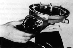
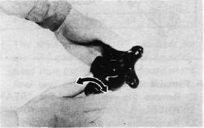
2. Universal joint
a. There should be no noticeable play in the universal joint bearings. If there is any play in the bearing, replace the universal joint assembly.
b. Move the universal joint up and down and from side to side. The universal joint should move smoothly. Without tightness, binding or rough spots that could indicate damaged bearings. If damaged, replace the universal joint assembly.
C. Reinstallation
When installing the drive shaft and the universal joint, reverse the removal procedure. Note the following points:
1. Lubricate the shaft splines with molybdenum di-sulfide grease.
2. Tighten the universal joint securing bolts and final gear case securing nuts with the specified torque:
Final gear case: 4.2 m-kg (30.4 ft-lb)
Universal joint: 4.4 m-kg (31.8 ft-lb)
- Printer-friendly version
- Log in to post comments