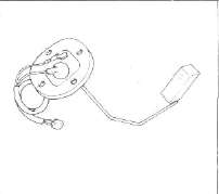
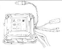
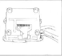
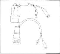
Sender locations
HTML clipboard
XJ750

System Components
|
Sidestand switch |
Brake fluid level sender |
Engine oil level sender |
|
|
|
|
|
Battery fluid level sender |
Headlight bulb |
|
|
Tail/Brake light bulb |
||
|
|
|
|
|
Fuel level sender |
Computerized monitor |
LCD panel |
|
|
|
|
|
Computer unit |
"Check" switch |
"Warning" switch |
|
|
|
|
Symbol Identification
|
|
Conductor |
|
Bulb (single filament) |
|
|
|
Crossing conductor (not joined) |
|
Bulb (Double filament) |
|
|
|
Conductors joined |
|
Wire connector |
|
|
|
Ground (earth) |
|
Diode |
|
|
|
Resistor (adjustable) |
|
Sender |
|
|
|
Switch |
|
|
Power input |
|
|
Switch
|
|
|
Power output |
|
|
Fuse |
|
Battery |
|
Color Code
|
Br |
Brown |
Gy |
Gray |
|
B |
Black |
G/R |
Green/ Red |
|
L |
Blue |
G/L |
Green/ Blue |
|
W |
White |
G/Y |
Green/Yellow |
|
Y |
Yellow |
L/W |
Blue/ White |
|
G |
Green |
Y/W |
Yellow/ White |
|
Y/G |
Yellow/ Green |
B/R |
Black/ Red |
|
W/R |
White/Red |
G/W |
Green/ White |
|
W/B |
White/ Black |
W/L |
White/Blue |
|
R/B |
Red/Black |
Y/B |
Yellow/Black |
NOTES ON TROUBLESHOOTING
Before checking the computerized monitor, check the following points:
Battery: Be sure to use a fully-charged battery for troubleshooting.
Motorcycle: The motorcycle to be inspected must be of standard specification (not modified after shipped from the factory).
1. No optional parts for users are fitted to the motorcycle. (Decoration light, etc.)
2. No modification is made to any part of the motorcycle. (Change in electrical circuits, etc.)
3. The level displayed on each monitor is correct, (the fuel, engine oil, brake fluid, and battery fluid levels are correct.)
4. All light bulbs are in good condition.
Tester: Use a Yamaha Pocket tester for checking of electrical parts.
- Printer-friendly version
- Log in to post comments


