SIGNAL SYSTEM Circuit diagram
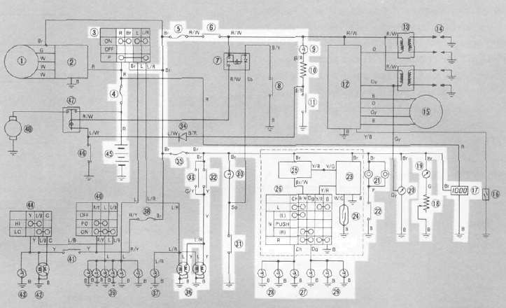
Signal system tests and checks
The battery provides power for operation of the horn, brakelight, indicator lights and flasher light. If none of the above operates, always check battery voltage before proceeding further. Low battery voltage indicates either a faulty battery, low battery water or a defective charging system. See page 6-9 "CHARGING SYSTEM" for checks of battery and charging system. Also check fuse condition. Replace any "open" fuses. There are individual fuses for various circuits (see complete Circuit Diagram).
1. Horn does not work
|
Check for voltage (12V) on "Br" lead at horn terminal. |
No voltage ► |
Check wiring circuit from fuse to horn terminal. |
|
Voltage OK ▼ |
||
|
Check for voltage on "P" lead at "HORN" switch connector. |
No voltage ► |
Wiring circuit from horn to "HORN" switch is faulty, repair. |
|
Voltage OK ▼ |
||
|
Check for continuity of "HORN" switch. |
No continuity |
"HORN" switch is faulty, replace. |
|
Continuity ▼ |
||
|
Adjust horn, replace if damaged. |
||
2. Brake light does not work a. Front brake
|
Check for voltage (12V) on "Br" Lead at front brake switch connector |
No voltage |
Check wiring circuit from fuse to brake switch connector. |
|
Voltage OK ▼ |
||
|
Check for voltage (12V) on "Gy" lead at front brake switch connector while applying brake. |
No voltage |
Front brake switch is faulty, replace |
|
Voltage OK ▼ |
||
|
Check for voltage (12V) on "Y" lead at brake light bulb socket while applying brake. |
No voltage |
Wiring circuit from brake switch to Brake light bulb socket is faulty, repair. |
b. Rear brake
|
Check for voltage (12V) on "Br" lead at rear brake switch connector. |
No voltage |
Check wiring circuit from fuse to brake switch connector. |
|
Voltage OK ▼ |
||
|
Check for voltage (12V) on "Y" lead at rear switch connector while applying brake. |
No voltage |
Rear brake switch is faulty or maladjustment, replace or adjust. |
|
Voltage OK ▼ |
||
|
Check for voltage (12V) on "Y" lead at brake light bulb socket while applying brake, |
No voltage |
Wiring circuit from brake switch to brake light bulb socket is faulty, repair. |
3. Flasher lights (left and/or right) do not work
|
Check for voltage (12V) on "Br" lead at flasher relay terminal. |
No voltage |
Check wiring circuit from fuse to flasher relay terminal. |
|
Voltage OK ▼ |
||
|
Check for voltage (12V) on "Br/W" lead at flasher relay terminal. |
No voltage |
Flasher relay is faulty, replace. |
|
Voltage OK ▼ |
||
|
Check for voltage (12V) on "Br/W" lead at "TURN" switch connector. |
No voltage |
Wiring circuit from flasher relay to "TURN" switch is faulty, repair. |
|
Voltage OK ▼ |
||
|
Check for voltage (12V) on "Ch" and/or "Dg" lead at "TURN" switch connector. |
No voltage |
"TURN" switch is faulty, replace. |
|
Voltage OK ▼ |
||
|
Check for voltage (12V) at left and/or right flasher (front and/or left bulb socket. |
No voltage |
Wiring circuit from "TURN" switch to flasher bulb is faulty, repair. |
Self-cancelling flasher system
1. Description
The self-cancelling flasher system turns off the turn signal after a period of time or distance involved in turning or changing lanes. Generally, the signal will cancel after either 10 seconds, or 150 meters (490 feet), whichever is greater. At very low speed, the function is determined by distance; at high speed, especially when changing speeds the cancelling determination is a combination of both times and distance.
2. Operation
The handlebar switch has three positions:
L (left), OFF, and R (right). The switch lever will return to the "OFF" position after being pushed to L or R, but the signal will function. By pushing the lever in, the signal may be cancelled manually.
3. Inspection
If the flasher self-cancelling system should become inoperative, proceed as follows: a. Pull of the 6-pin connector from the flasher cancelling unit, and operate the handlebar switch.
If the signal operates normally in L, R, and OFF, the following are in good condition.
1) Flasher relay
2) Bulb
3) Lighting circuit
4) Handlebar switch light circuit
If 1) through 4) are in good condition, the following may be faulty:
1) Flasher cancelling unit.
2) Handlebar switch reset circuit
3) Speedometer sensor circuit
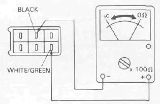
b. Pull off the 6-pin connector from the flasher cancelling unit, and connect a tester (ohms x 100 range) across the white/green and the black leads on the wire harness side. Turn the speedometer shaft If the tester needle swing back and forth between 0 and co, the speedometer sensor circuit is in good condition. If not, the sensor to wire harness may be inoperative.
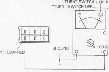
c. Pull the 6-pin connector from the flasher cancelling unit Check if there is continuity between the yellow/red lead on the wire harness side and the chassis.
"TURN" switch OFF: oo "TURN" switch L or R: 0 il
If the tester needle does not swing as indicated above, check the handlebar switch circuit and wire harness.
d. If no defect is found with the above three check-ups and the flasher cancelling system is still inoperative, replace the flasher cancelling unit.
e. If the signal flashes only when the handlebar switch lever is turned to L or R and it turns off immediately when the handlebar switch lever returns to center, replace the flasher cancelling unit
- Printer-friendly version
- Log in to post comments