TCI Identification
The following is a guide to determing if a used TCI is appropriate for a given machine:
The following is a guide to determing if a used TCI is appropriate for a given machine:
Cylinder head cover
Place head cover on a surface plate. There should be no warpage. Correct by re-surfacing as follows:
Place # 400 or # 600 grit wet sandpaper on surface plate and re-surface head cover using a figure-eight sanding pattern. Rotate head cover several times to avoid removing too much material from one side.
Cylinder head
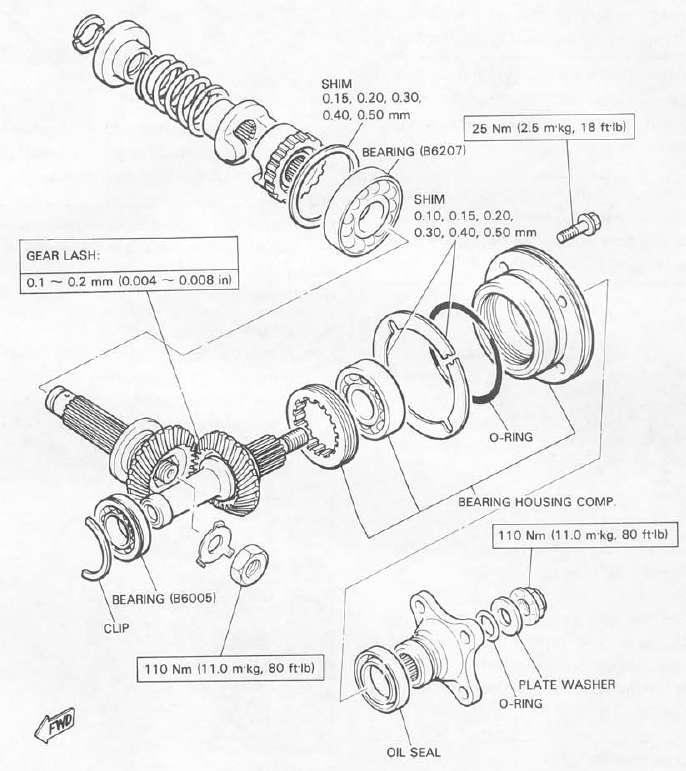
MIDDLE GEAR/DAMPER


a. Middle gear lash 0 2 mm (0.008 in)
d. Measure the gap between the driven gear bearing housing flange and the crankcase with a feeler gauge. This is the shim size required.
Final gear disassembly
1. Remove the nuts and bolts holding the bearing housing.
2. Remove the ring gear assembly and thrust washer from the final gear case.

3. Remove the self-locking nut from drive pinion by using the holding tool (special tool) and remove the coupling.
Oil pump
1. Check the clearance between housing and outer rotor.
Standard clearance: 0.03 — 0.09 mm (0.0012 — 0.0035 in)
2. Check the clearance between outer rotor and inner rotor.
Standard clearance: 0.03 — 0.08 mm (0.0012 — 0.0031 in)
3. Check the plunger for scratches and wear.

Cylinder head and cylinder
1. Remove the cylinder head cover.
2. Remove the left crankcase cover (pickup coil cover).
3. Remove the cam chain tensioner.

Clutch adjustment
This model has two clutch cable length adjusters. The cable length adjusters are used to take up slack from cable stretch and to provide sufficient free play for proper clutch operation. Normally, once the clutch cable length adjuster (crankcase) is properly set; the only adjustment required is maintenance of free play at the clutch cable length adjuster (handlebar lever).
Cam chain adjustment
This model has been equipped with the automatic cam chain tensioner. No adjustment is necessary.
Ignition timing check
1. Ignition timing is checked with a timing light by observing the position of the stationary pointer and the marks stamped on the timing plate.
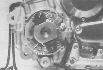
Pick-up coil assembly
1. Remove the alien bolt that holds the timing plate.

2. Remove the pick-up coil securing screws and remove the pick-up coil assembly.

Shifter
TRANSMISSION

3. Crankcase assembly a. Apply Yamaha bond #4 sealant or equivalent to the crankcase mating surface. Be very careful not to allow any sealant to come in contact with the oil gallery "O-ring" and crankshaft bearings. It is extremely important, however, that sealant be applied around the case stud holes. Apply sealant to within 2 — 3 mm (0.08 — 0.12 in) of the bearings.