CYLINDER
1. Inspect the cylinder walls for vertical scratches and Rebore or Replace cylinder as required.

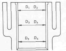
2. Measure the cylinder inside diameter.

NOTE:
Obtain measurements at three depths by placing measuring instrument parallel to and at right angles to crankshaft.
Out of specification -> Rebore cylinder, and replace piston and piston rings.
|
|
Standard |
Wear Limit |
|
Cylinder bore: C |
68.000-68.005 mm |
68.1 mm |
|
Cylinder taper: T |
0 |
0.05 mm |
C= Maximum D
T= Maximum of D1or D2 minus Minimum of D5 or D6
PISTON, PISTON RING, AND PISTON PIN

Piston 1 . Measure the piston skirt diameter "P" 2
NOTE:
Measure the piston skirt diameter where the distance 1 is 5.0 mm (0.197 in) from the piston bottom edge.
|
|
Piston Size P |
|
Standard |
68.00 mm |
|
Oversize 2 |
68.50 mm |
|
Oversize 4 |
69.00 mm |
2. Measure the piston clearance
Piston Clearance = Cylinder inside diameter "C" minus Piston skirt diameter "P"
Out of specification -> Rebore cylinder, and replace piston and piston rings.
Piston Clearance: 0.06 - 0.08 mm (0.0024 - 0.0031 in)

Piston Ring 1 .
Measure ring side clearance. Use a feeler gauge.
Out of specification -> Replace piston.
NOTE:
Clean carbon from piston ring grooves and rings before measuring side clearance.
|
|
Piston Ring Side Clearance (Limit): |
|
|
Top Ring |
0.15 mm (0.006 in) |
|
|
2nd Ring |
0.15 mm (0.006 in) |
|
2. Position the piston ring in cylinder.
NOTE:
Insert a ring into cylinder, and push it approximately 2 0 mm (0.8 in) into cylinder. Push ring with piston crown so that ring will be at a right angle to cylinder bore.

3. Measure the ring end gap. Replace if out of specification.
NOTE:
You cannot measure end gap on expander spacer of oil control ring. If oil control ring rails show excessive gap, replace all three rings.
|
|
End Gap Limit (Installed): |
|
Top Ring |
1.0 mm (0.040 in) |
|
2nd Ring |
1.0 mm (0.040 in) |
|
Oil Ring |
1.5 mm (0.060 in) |
Piston Ring Oversize

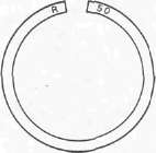
•Top and 2 nd piston ring Oversize top and middle ring sizes are stamped on top of ring.
|
Oversize 2 |
0.50 mm (0.0197 in) |
|
Oversize 4 |
1.00 mm (0.0394 in) |

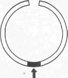
• Oil control ring Expander spacer of bottom ring (oil control ring) is color-coded to identify sizes.
|
Size |
Color |
|
Oversize 2 |
Red |
|
Oversize 4 |
Yellow |
Piston Pin
1. Lubricate piston pin (Lightly)

2. Install:
• Piston pin 1 into small end of connecting rod 2.
3. Check for free play
Free play -> Inspect connecting rod for wear.
Wear -> Replace connecting rod and piston pin.

4. Position the piston pin 1 into piston.
5. Check for free play in piston.
Free play -> Replace piston pin and/or piston.
- Printer-friendly version
- Log in to post comments
