
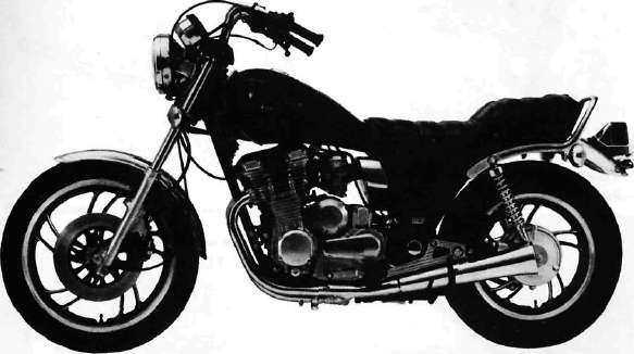
YAMAHA
XJ650LJ and XJ650LK (Turbo)
NOTICE
This manual was written by the XJ Owners Group to replace the composite set of manuals and suppliments offered by Yamaha Motor Company primarily for use by Yamaha dealers and their qualified mechanics.
It is not possible to put an entire mechanic's education into one manual, so it is assumed that persons using this book to perform maintenance and repairs have a basic understanding of the mechanical concepts and procedures inherent to motorcycle repair technology. Without such knowledge, attempted repairs or service to this model may render it unfit to use and/or unsafe.
Particularly important information is distinguished in this manual by the following notations:
NOTE:
A NOTE provides key information to make procedures easier or clearer.
CAUTION:
A CAUTION indicates special procedures that must be followed to avoid damage to the motorcycle.
WARNING:
A WARNING indicates special procedures that must be followed to avoid injury to a motorcycle operator or person inspecting or repairing the motorcycle.
CHAPTER 1. GENERAL INFORMATION
MOTORCYCLE IDENTIFICATION
A. Frame Serial Number
The frame serial number is stamped into the right side of the steering head pipe.
B. Engine Serial Number
The engine serial number is stamped into the elevated part of the right rear section of the engine.
NOTE:
The first three digits of these numbers are for model identifications; the remaining digits are the unit production number.
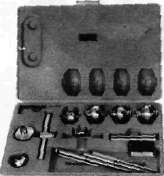
SPECIAL TOOLS
The proper special tools are necessary for complete and accurate tune-up and assembly. Using the correct special tool will help to prevent damage from improper tools or improvised techniques.
A. For Tune-up
1. Compression gauge
2. Timing light
3. Tachometer
4. Tappet adjusting tool P/N. 90890-01245-00
This tool is necessary to replace valve adjusting pads. This can also be used for the XS750, XS850 and XS1100.
5. Vacuum gauge
P/N. TLU-11080-30-02
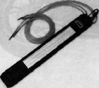
This gauge is needed for carburetor synchronization.
B. For Engine Service
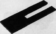
1. Clutch hub holder P/N. TLM-90910-42-00
This tool is used to hold the clutch when removing or installing the clutch boss lock nut.
Valve guide reamer P/N. 90890-01227-00
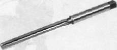
This must be used when replacing the valve
guide
3. Valve seat cutter
P/N.TLM-90910-43-20
This tool is needed to re-surface the valve seat.
4. Valve guide remover P/N. 90890-01225-00

This must be used to remove the valve guides,
5. Valve guide installer P/N. 90890-04017-00

This tool is needed for proper installation of the valve guides.
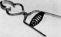
6. Valve spring compressor P/N. 90890-01253-00

This tool must be used for removing and installing the valve assemblies.
7. Piston ring compressor P/N. 90890-04044-00
This is used to compress piston rings when installing the cylinder.
8. Piston base
P/N. 90890-01067-00
Use 4 of these to hold the pistons during cylinder installation.
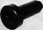
9. Rotor puller
P/N. 90890-01080-00

This tool is needed to remove the A.C. Generator rotor.
10. Rotor puller attachment P/N. 90890-04052-00

This tool is needed when removing the A.C. Generator rotor together with the rotor puller.
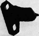
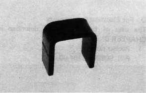
11. Rotor holding tool P/N. 90890-04043-00

This tool is used to hold the A.C. Generator rotor during removal and installation.
12. Dial gauge stand
P/N. 90890-01258-00

This tool is needed to hold the dial gauge.
13. Dial gauge
P/N. 90890-03097-00

This dial gauge is used to determine piston position for correct timing.
C. For Shaft Drive Service
1. Middle drive pinion holder P/N. 90890-04051-00
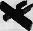
This tool is needed when measuring gear lash.
2. Middle and final gear holding tool P/N. 90890-01229-00
This tool is needed when measuring gear lash.
3. Gear lash measurement tool (Final gear) P/N. 90890-01230-00

This tool is needed when measuring gear lash for final gear.
4. Final gear holding tool P/N. 90890-01254-00

This tool is needed when measuring gear lash.
5. Damper compressor P/N. 90890-04011-00
This tool is needed to disassemble and reassemble the middle gear damper.
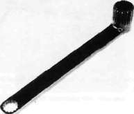
6. Middle drive shaft nut wrench P/N. 90890-04045-00
This tool is used to loosen and tighten the drive shaft nut,
7. Middle drive shaft holder P/N. 90890-04046-00

This tool is needed when loosening and tightening the drive shaft nut.
8. Drive pinion bearing retainer remover P/N. 90890-04050-00

This tool is used to loosen and tighten the final gear drive pinion bearing retainer.
9. Armature shock puller (M10 x 1.25) P/N. 90890-01290-00, 90890-01291-00


These tools are used to remove the final gear drive pinion.
10. Crank installer adapter (M10x1.25/M14x1.5) P/N. 90890-01277-00

This adapter is needed when using the armature shock puller.
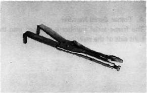
11. Drive shaft puller P/N. 90890-04012-00

This tool is used to remove the drive shaft.
12. Slide hammer
P/N. 90890-01083-00, 90890-01084-00
These tools are used to remove the drive shaft.
13. Front fork cylinder comp. holder P/N. 90890-01300-00

This tool is used to loosen and tighten the front fork cylinder comp. holding bolt.
D. For Electrical Components
The uses of these tools are described in CHAPTER 6. 1. Pocket tester
P/N. 90890-03104-00

2. Electro tester
P/N. 90890-03021-00

- Printer-friendly version
- Log in to post comments