Chapter 1, Introduction
Chapter 1, Introduction
YAMAHA
XJ650LJ and XJ650LK (Turbo)
NOTICE
This manual was written by the XJ Owners Group to replace the composite set of manuals and suppliments offered by Yamaha Motor Company primarily for use by Yamaha dealers and their qualified mechanics.
It is not possible to put an entire mechanic's education into one manual, so it is assumed that persons using this book to perform maintenance and repairs have a basic understanding of the mechanical concepts and procedures inherent to motorcycle repair technology. Without such knowledge, attempted repairs or service to this model may render it unfit to use and/or unsafe.
Particularly important information is distinguished in this manual by the following notations:
NOTE:
A NOTE provides key information to make procedures easier or clearer.
CAUTION:
A CAUTION indicates special procedures that must be followed to avoid damage to the motorcycle.
WARNING:
A WARNING indicates special procedures that must be followed to avoid injury to a motorcycle operator or person inspecting or repairing the motorcycle.
CHAPTER 1. GENERAL INFORMATION
MOTORCYCLE IDENTIFICATION
A. Frame Serial Number
The frame serial number is stamped into the right side of the steering head pipe.
B. Engine Serial Number
The engine serial number is stamped into the elevated part of the right rear section of the engine.
NOTE:
The first three digits of these numbers are for model identifications; the remaining digits are the unit production number.
SPECIAL TOOLS
The proper special tools are necessary for complete and accurate tune-up and assembly. Using the correct special tool will help to prevent damage from improper tools or improvised techniques.
A. For Tune-up
1. Compression gauge
2. Timing light
3. Tachometer
4. Tappet adjusting tool P/N. 90890-01245-00
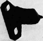
This tool is necessary to replace valve adjusting pads. This can also be used for the XS750, XS850 and XS1100.
5. Vacuum gauge
P/N. TLU-11080-30-02
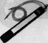
This gauge is needed for carburetor synchronization.
B. For Engine Service
1. Clutch hub holder P/N. TLM-90910-42-00
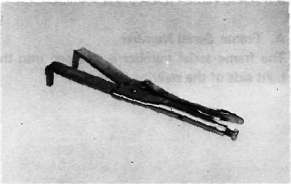
This tool is used to hold the clutch when removing or installing the clutch boss lock nut.
Valve guide reamer P/N. 90890-01227-00

This must be used when replacing the valve
guide
3. Valve seat cutter
P/N.TLM-90910-43-20
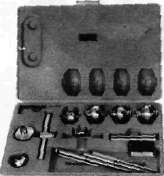
This tool is needed to re-surface the valve seat.
4. Valve guide remover P/N. 90890-01225-00

This must be used to remove the valve guides,
5. Valve guide installer P/N. 90890-04017-00

This tool is needed for proper installation of the valve guides.
6. Valve spring compressor P/N. 90890-01253-00

This tool must be used for removing and installing the valve assemblies.
7. Piston ring compressor P/N. 90890-04044-00
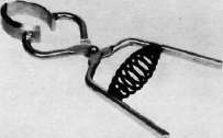
This is used to compress piston rings when installing the cylinder.
8. Piston base
P/N. 90890-01067-00
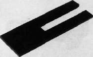
Use 4 of these to hold the pistons during cylinder installation.
9. Rotor puller
P/N. 90890-01080-00

This tool is needed to remove the A.C. Generator rotor.
10. Rotor puller attachment P/N. 90890-04052-00

This tool is needed when removing the A.C. Generator rotor together with the rotor puller.
11. Rotor holding tool P/N. 90890-04043-00

This tool is used to hold the A.C. Generator rotor during removal and installation.
12. Dial gauge stand
P/N. 90890-01258-00

This tool is needed to hold the dial gauge.
13. Dial gauge
P/N. 90890-03097-00

This dial gauge is used to determine piston position for correct timing.
C. For Shaft Drive Service
1. Middle drive pinion holder P/N. 90890-04051-00
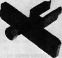
This tool is needed when measuring gear lash.
2. Middle and final gear holding tool P/N. 90890-01229-00
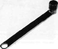
This tool is needed when measuring gear lash.
3. Gear lash measurement tool (Final gear) P/N. 90890-01230-00

This tool is needed when measuring gear lash for final gear.
4. Final gear holding tool P/N. 90890-01254-00

This tool is needed when measuring gear lash.
5. Damper compressor P/N. 90890-04011-00
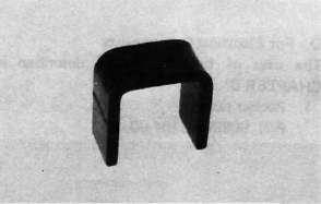
This tool is needed to disassemble and reassemble the middle gear damper.
6. Middle drive shaft nut wrench P/N. 90890-04045-00

This tool is used to loosen and tighten the drive shaft nut,
7. Middle drive shaft holder P/N. 90890-04046-00

This tool is needed when loosening and tightening the drive shaft nut.
8. Drive pinion bearing retainer remover P/N. 90890-04050-00

This tool is used to loosen and tighten the final gear drive pinion bearing retainer.
9. Armature shock puller (M10 x 1.25) P/N. 90890-01290-00, 90890-01291-00


These tools are used to remove the final gear drive pinion.
10. Crank installer adapter (M10x1.25/M14x1.5) P/N. 90890-01277-00

This adapter is needed when using the armature shock puller.
11. Drive shaft puller P/N. 90890-04012-00

This tool is used to remove the drive shaft.
12. Slide hammer
P/N. 90890-01083-00, 90890-01084-00
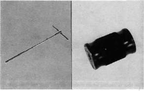
These tools are used to remove the drive shaft.
13. Front fork cylinder comp. holder P/N. 90890-01300-00

This tool is used to loosen and tighten the front fork cylinder comp. holding bolt.
D. For Electrical Components
The uses of these tools are described in CHAPTER 6. 1. Pocket tester
P/N. 90890-03104-00

2. Electro tester
P/N. 90890-03021-00

Special Features of the Turbo Models
Special Features of the Turbo ModelsMAJOR FEATURES
YAMAHA INDUCTION CONTROL SYSTEM
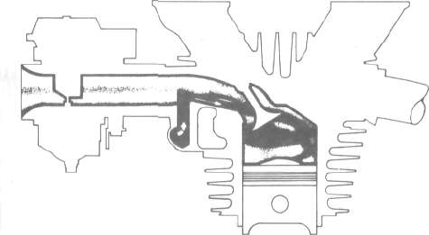
This system has subintake ports. The cross-section area of these subintake port is smaller than that of main intake ports. The smaller ports enter the main ports just above the intake valve seat and at such an angle that their charge is directed around the walls of the cylinder; this results in a swirling effect as the mixture is compressed into the combustion chamber.
The subintake ports for all four cylinders are interconnected. Since only one cylinder is on the intake stroke at a time, the subintake port for that cylinder draws mixture from the other three carburetors and subintake ports. When the piston is moving down and the intake valve opens, a vacuum is created in the main and subintake ports. But since the area of the subintake port is so much smaller, the mixture moves faster through it than through the main intake port. The charge from the subintake port, therefore, blasts around the wall of the cylinder, swirling the entire intake charge. This results in more complete burning of the air-fuel mixture.
YAMAHA TURBO SYSTEM
GENERAL DESCRIPTION OF THE TURBOCHARGER
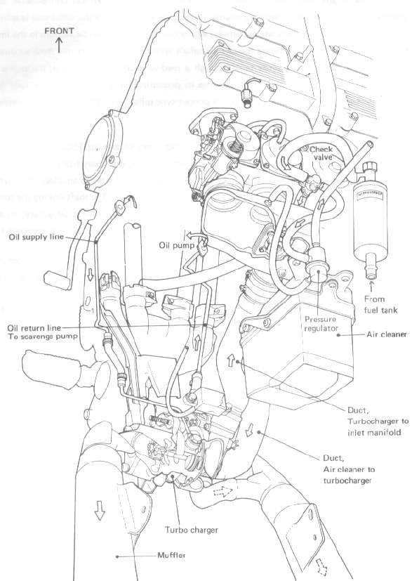
Yamaha has largely eliminated "turbo lag", a phenomenon which afflicts conventional turbo systems when the throttle is snapped open at low engine speeds. Since the turbo unit is spinning too slowly to provide an adequate air supply, a conventional turbo suffers a vacuum in the intake tract and hesitates before building speed. Yamaha's system, however, provides fresh air directly from the air cleaner to the surge tank through a reed-valve-controlled passage; the engine can build speed freely until the turbo unit resumes its pressurizing effect and closes the reed valve. Another notable feature in the surge tank is a poppet-type relief valve that backs up the wastegate in preventing excess boost in the intake side.
The turbocharger unit is subjected to exhaust temperatures of around 1500°F; it is therefore positioned behind the crankcase and below the swingarm pivot, well away from the rider and the fuel system. The turbo unit itself, a Mitsubishi TC03-O6A, is the world's smallest: the turbine diameter is only 39 mm, and it can spin safely up to 210,000 rpm. The shaft linking the turbine to the intake compressor is pressure-lubricated from the crankshaft's main oil gallery; an additional scavenging pump retrieves the oil from the turbo unit, ensuring a constant, adequate flow.
The exhaust system has an inner wall of stainless steel from the header pipes to the turbocharger. A patented exhaust manifold links the #1 and #4 exhaust pipes together and the #2 and #3 pipes together before they enter the turbocharger; this design provides even exhaust pulsing to drive the turbine and results in greater midrange torque. A wastegate in the manifold bleeds off excess exhaust pressure to prevent too much boost in the intake. The left-side muffler receives the exhaust gas from the turbo unit, and the right-side muffler handles excess from the wastegate.
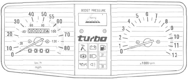
INSTRUMENT PANEL & PICTOGRAPHIC COMPUTER MONITOR SYSTEM
The XJ650 turbo computer monitor system features:
1. Easy-to-see pictographic displays; a further improvement upon the XJ750 computer monitor.
2. Highly reliable liquid crystal displays in three colors, specifically designed for motorcycle application.
1} Red display for safety
• Sidestand retraction
• Disc brake fluid amount
• Engine oil amount
• Fuel amount
2) Blue display for electrics
• Battery liquid amount
• Headlight
• Tail/brake light
3) Green display for remaining fuel amount
• Four-stage display for remaining fuel amount
DISPLAY PANEL
1 This indicator is displayed when the sidestand is not retracted.
2 This indicator is displayed when the brake fluid level is below specification in the front brake master cylinder.
3 This indicator is displayed when the engine oil level is low.
4 This indicator is displayed when the battery fluid level is low.
5 This indicator is displayed when the headlight bulb is burned out.
6 This indicator is displayed when the taillight and/or brake light bulbs are burned out.
7 This indicator is displayed when the fuel level is low.
TURBO 650 FAIRING
The fairings on Yamaha's innovative new models represent more than just handsome cosmetics. Indeed, from their inception to their final rendering, form was designated secondary to function. In designing a fairing; two of the most important aerodynamic factors are wind resistance and front wheel lift force. Through extensive wind-tunnel testing, Yamaha engineers crafted a fairing for the Seca Turbo which significantly reduces these effects. Every component down to the rear-view mirrors was designed with aerodynamic efficiency in mind. The coefficient of drag, a measurement of wind resistance, is among the lowest in the world for a road machine. A reduction of about 10% was achieved in front wheel lift force over a similar machine not equipped with a fairing.
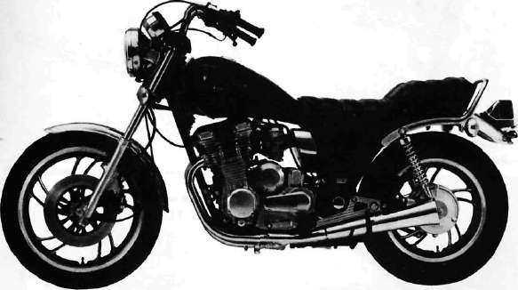
Yamaha maintains its lead in advanced high-performance technology with the introduction of the XJ650LJ, featuring the Yamaha Turbo System. This system uses the power of the exhaust gases, normally wasted, to spin a turbine which supercharges the intake of the air fuel mixture. The system goes far beyond the unrefined, bolt-on turbochargers offered by accessory companies. The Yamaha Turbo System is a fully integrated combination of sophisticated engineering features which virtually eliminates the problems of conventional turbocharging while enhancing its advantages. The result is a lightweight, nimble-handling machine which performs like a superbike with an engine twice as large. Yamaha is proud to rewrite the books on high-performance motorcycling!

