INSPECTION

1. Check
• teeth of middle gear for discoloration/Pitting/Wear. If necessary, replace all middle gears as a set.
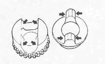
• Damper cam surfaces for wear/Unsmooth action. Replace if necessary.
2. Check bearing movement. Rotate the race by finger and replace if rough.
ASSEMBLY AND ADJUSTMENT
1. Select proper middle-drive-gear shim.
NOTE:
Select proper middle-drive-gear shim whenever crankcase and/or middle gears are replaced.


Shim thickness calculation:
Calculate shim thickness using formula below:
Shim thickness (A) = c - a - b
a = 43 plus or minus the number printed on end of middle drive shaft.
b = a bearing thickness. (Considered constant)
c = 60 plus the number found on the upper crankcase half near the main bearing selection numbers:
For example:
If middle drive shaft is marked "+03" and crankcase is tamped "45".
a= 43 + 0.03 = 43.03 mm
c= 63 + 0.45 = 60.45 mm
b= 16.94 mm (Constant)
A = 60.45 - 43.03 - 16 .94 = 0.48 Calculated shim thickness is 0.48 mm.
Available shim thickness: 0.15 mm, 0.30 mm, 0.40 mm, 0.50 mm
Because shim can only be selected in 0.05 mm increments, use following chart to round off the hundredths digit of calculated thickness, and select appropriate shim.
|
Hundredths digit |
Rounded value |
|
0,1,2 |
0 |
|
3,4,5,6 |
5 |
|
7,8,9 |
10 |
In above example, calculated shim thickness is 0.48 mm. The chart instructs you, however, to round off the 8 to 10. Thus you should use two 0.50 mm shims.

2. Install:
• Middle drive shaft bearing.
• Middle drive pinion
• Lock washer (New)
• Nut
3. Tighten the nut
4. Bend lock washer of nut into middle drive shaft slot using a center punch.

5. Assemble:
• Damper cam 1
• Spring 2
• Spring seat 3
• Spring retainer
Use a Press and Damper Compressor (90890-04090)4.

NOTE:
Install the driven damper cam onto the drive pinion shaft with the cam lobes positioned 90° from the row of shaft oil holes 1. Positioning tolerance is ±1 spline (15°) from the 90° position.
Middle Drive Shaft Nut: 110 Nm (11 m-kg, 8 0 ft-lb)
6. Install:
• Bearing housing (onto the drive pinion shaft)
• Flange
• O-ring (New) (onto the drive pinion shaft)

7. Tighten:
• Flange holding nut
Flange Holding Nut: 90 Nm (9.0 m-kg, 65 ft-lb) LOCTITE®

8. Lock the thread on the holding nut with a center punch.
- Printer-friendly version
- Log in to post comments
