Chapter 5, CARBURETION
Chapter 5, CARBURETIONGeneral Information and Operation
General Information and OperationCARBURETION

CARBURETOR
1 Piston valve spring
2 Starter plunger assembly
3 Upper bracket4 O-ring5 Joint
6 Lower bracket
7 Throttle stop screw
8 Synchronizing screw
9 Washer
10 Main jet
11 Valve seat assembly
12 Float
13 Gasket
14 Drain screw
15 Float chamber
16 Pilot jet
17 Needle jet
18 Spring
19 Piston valve
20 Diaphragm
21 Jet needle assembly
|
SPECIFICATIONS |
|
|
Main jet |
= 105 |
|
Main air jet |
= 120 |
|
Jet needle |
5FZ83 |
|
Needle jet |
Y-2 |
|
Pilot jet |
#37.5 |
|
Pilot air jet |
= 140 |
|
Fuel level |
3.0 ± 1.0 mm |
|
Float height |
17.5+ 1.0 mm |
|
Pilot screw |
2-1/2 ± 1/2 |
|
Float valve seat |
0 2.3 |
|
Engine idle speed |
1,050 ± 50r/min |
SECTION VIEW
|
A |
|
AIR |
|
B |
|
MIXTURE |
|
C |
|
FUEL |


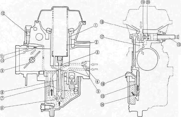
1 Piston valve
2 Spring
3 Jet needle
4 Main air jet
5 Pilot air jet
6 Main jet
7 Pilot jet
8 Needle jet
9 Throttle valve
10 Bypass hole
11 Pilot outlet
12 Pilot screw
13 Starter plunger
14 Starter jet
15 Starter bleed pipe
16 Starter air bleed
17 Mixture outlet
18 Air inlet
19 Starter half position
20 Starter full position
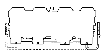
AIR CLEANER AND CRANKCASE VENTILATIONS SYSTEM
Refer to "CHAPTER 2" for air cleaner maintenance.
|
A |
|
FRESH AIR |
|
B |
|
BLOW BY GAS |


1 Air cleaner 2 Carburetor
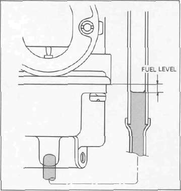
Fuel Level Adjustment
Fuel Level Adjustment1. Measure fuel level. Adjust if out of specification.

Measurement steps:
• Place the motorcycle on a level surface.
• Shim the center stand as required to level from side to side using a level across the carb bank
NOTE: The carburetor bank can be used as a level. Set petcock to "PRI" or use temporary fuel supply. Check that the fuel level of one carb against both left and right sides of bank is be equal.
• Use a garage jack under the engine or block under the front wheel to ensure that the carburetor is positioned vertically by raising the front wheel until the rear is touching the ground.
• Take measurements at center of closest outboard Carburetor body
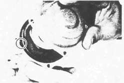
• Connect the Fuel Level Gauge 1 (90890-01312) to the drain opening 2 .
• Loosen the drain screw 3 and start the engine.
• Check the fuel level, one carburetor at a time.
Fuel Level a: bottom of meniscus to bottom edge of the carburetor body 3.0 ±1.0 mm (0.12 ± 0.04 in)
NOTE:
• Raise the hose as high as possible before opening the drain screw, and slowly lower the hose into position to ensure no air is trapped in the hose.
• Once the drain screw is open, lower it into position. Never raise the hose while taking the measurements. Raising the hose will make the measurement inaccurate.
• Set the petcock to "PRI" or use a temporary fuel supply
• Watch the level carefully for a few moments after taking the reading. If the level slowly rises, the float needle valve is leaking and must be polished or replaced.
2. Adjust:
• Fuel level (If necessary)

Adjustment steps:
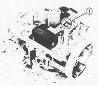
• Remove the carburetors.
• Adjust float level by bending the float tang 1 slightly.
• Repeat the procedure for the other carburetors.
NOTE: It's easy to lose track of the carb #s once you flip them upside down to make that float tang adjustment. Marking the #1 carb with a piece of tape will help keep them identified.
Carburetor Overhaul
Carburetor Overhaul
REMOVAL
1. Remove carburetor assembly. Refer to engine removal section.
NOTE: The following parts can be cleaned and inspected without disassembly.
• Piston valve
• Jet needle
2. Disconnect:
• Drain hoses
• Fuel hoses
• Throttle cable
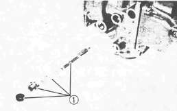
3. Number each carburetor before removing it from carburetor brackets.
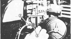
4. Loosen the starter lever screws

5. Remove:
• Starter lever shaft 1
• Starter levers 2
• Lower bracket 3
NOTE:
When separating the carburetors be sure not to lose the small spring 4 that may fall out. This spring connects the throttle levers.

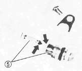
6. Remove:
• Upper bracket 1
• Carburetor joint 2
• Carburetors
DISASSEMBLY

1. Remove:
• Vacuum chamber cover 1
• Spring 2
• Vacuum piston 3
• Jet needle 4
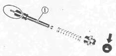
2. Remove the starter plungers 1

3. Remove:
• Float chamber cover
• Float pin 1
• Float 2
• Needle valve 3
• Valve seat 4

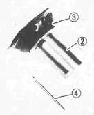
4. Remove:
• Pilot jet 1
• Main jet 2
• Needle jet 3
• Pilot air jet 4
NOTE:
Remove the needle jet toward the vacuum piston.
Inspection and Assembly
Inspection and AssemblyINSPECTION
1. Inspect the starter plunger 1 for damage. Replace if damaged or worn.
• Vacuum piston 2. Replace if scratched/worn.
•Throttle valve diaphragm 3. Replace if torn or damaged.
•Jet needle 4. Replace if bent or worn.
• Needle valve and valve seat 5. Replace if worn.
• Float. Replace if damaged or punctured.
• Carburetor body
• Fuel passage. Clean contaminated or plugged passages.
•Jets. Clean if contaminated or plugged.

• O-rings (Carburetor joint) 6
Wear/Damage -► Replace.
NOTE:
• Wash the carburetor in a petroleum-based solvent. Do not use any caustic carburetor cleaning solutions.
• Blow out all passages and jets with compressed air.
• Do not attempt to push wire through brass jets. If necessary, use a single bristle from a stiff nylon brush.
ASSEMBLY:
1. Assemble the carburetors
NOTE:
To assemble the carburetors, reverse the disassembly procedures. Pay close attention to the installation of the vacuum piston diaphragm and the location of each jet.
FLOAT HEIGHT ADJUSTMENT
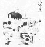
1. Measure float height a
Float height measurement steps:
• Hold the carburetor in an upside down position.
• Incline the carburetor at 60°--70° (so that the end of the float valve does not hang down as a result of float weight).
• Measure the distance from the mating surface of the float chamber (gasket removed) to the too of the float.
NOTE:
The float should be just resting on, but not depressing, the spring loaded inlet needle.
Float Height: 17.5 ± 1.0 mm (0.69 ± 0.04 in)
Float height adjustment steps:
• Remove the float.
• Adjust float height by bending the float tang 1 slightly.
• Repeat the procedure for other carburetors.
NOTE:
Float height is an approximation of fuel level. For best results, fine tune fuel level. See Carburetor Adjustments.
Installing Carbs into old, dry rubber manifolds
Installing Carbs into old, dry rubber manifoldsINSTALLATION
1. Install carburetors: Reverse the removal steps.
Yeah, right...
Maxim X Carburetor Installation
A Technique for reinstalling old hardened intake boots. (Note: This will probably not work on other models with long boots)
This is not a Yamaha procedure. It was developed by Joe D. HAP and dv
Step 1. After soaking the rubber in a bucket of hot water, secure each air box boot to the carburetor with it's clamp.

Step 2. Slide the carbs in from the right hand side above the rubber intake manifolds on the engine and below the frame. The free end of the boot is usually much more flexible than the end that has been attached to a hot carburetor for 20 years and will flex. Take care not to pull the boots off the carbs, especially when easing #4 around the clutch cable. This is far easier to accomplish with at least two people. The rubber manifolds will also require some 'massaging' as the float bowls pass by.

Step 3, Once the carburetors are aligned with their respective intake manifolds, ease the air box boots into their holes. There are two lips that normally sit on either side of the airbox wall. Ignore them for now.
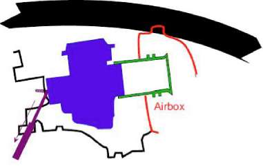
Step 4. Pull back on the carbs enough to gain clearance between the front and the manifolds. Rotate the front of the carbs down into position. Carefully examine all around each one to ensure the rubber has not folded in front of the carb. Use a hooked tool to pull any folds out as required.

Step 5, Push the carburetors forward into the manifolds. They will snap into place as the lip engages the groove on the carburetor. Secure with clamps. Massage the airbox boots into place with a long straight screwdriver. Now is the time to ensure the sealing lips are properly positioned with one lip on either side of the airbox.
After installation, set the throttle free-play. See Carburetor Adjustments for details.

Throttle Cable Free Play a: 2- 5 mm (0.08-0.20 in)