Chapter 4, COOLING SYSTEM
Chapter 4, COOLING SYSTEMDescription
DescriptionCOOLANT FLOW
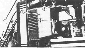
The coolant is circulated by an impeller type pump mounted on the right-hand crankcase and driven by a gear. The coolant is drawn by the pump from the bottom tank of the radiator, through the pipe 1, and discharged into the cylinder head and cylinder through the pipe 2. The coolant passes from the cylinder head through coolant ways and after circulating around combustion chamber jacketing enters the radiator upper tank via inlet pipe 3. The heated coolant from the engine then passes down through the finned tubes to the bottom tank of the radiator. These finned tubes present a large surface area to the air and dissipate the heat.

4 Radiator
5 Water pump
6 Thermostatic valve
Draining the System
Draining the SystemCOOLANT DRAINING
Do not remove the radiator cap when the engine and radiator are hot.

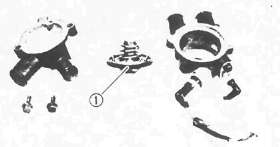
1. Remove:
•Cap retainer 1
Radiator cap 2

2. Place an open container under the engine.
3. Remove:
• Drain bolts 1, 2 & 3. Drain the coolant.
1 Drain bolt (Radiator) 2 Drain bolt (Radiator pipe) 3 Drain bolt (Cylinder)
Water Pump
Water PumpREMOVAL AND DISASSEMBLY
NOTE:
Be sure to drain the coolant before disassembly of the cooling system components.
1. Drain the engine oil


2. Remove:
•Water pump drive gear cover 1
•Water pump drive gear 2
Water pump drive gear bolt 3 is locked with LOCTITE®.
•Spacer 4

3. Remove:
• Water pump joint 1
• O-rings 2
4. Disconnect bypass hose 3

5. Remove:
• Radiator pipe 1
• Clutch cam shaft lever 2
• Clutch cover 3

5. Remove:
• Water pump cover 1
• O-ring 2
• Circlip 3
• Driven gear 4
• Dowel pins 5
• Circlip 6
• Impeller shaft 7
INSPECTION
1. Eliminate deposits from the impeller and water pump housing.

2. Inspect:
• Oil seal 1
• O-ring 2
Replace if worn or damaged.

3. Inspect:
• Impeller 1
• Driven gear 2
Replace if cracked, worn or damaged.
ASSEMBLY AND INSTALLATION

1. Install:
• Oil seal (Mechanical seal) 1 Use Water Pump Seal Installer (90890-04078) 2 and Handle (90890-04058).

2. Assembly:
• Water pump Reverse the disassembly procedures.
Water Pump Cover: 10 Nm (1.0m-kg, 7.2ft-lb)
3. Install:
• Clutch cover Refer to CHAPTER 3 "ENGINE ASSEMBLY AND ADJUSTMENT"

• Water pump joint 1 (With new O-rings 2)
Water Pump Joint: 10Nm(1.0mkg, 7.2ft-lb)
4. Connect the bypass hose

5. Install:
• Spacer 1
• Water pump drive gear 2
• Water pump drive gear cover 3
• Radiator pipe 4 (With new O-ring)
Water Pump Drive Gear: 12Nm (1.2m.kg, 8.7ft-lb) LOCTITE®
Water Pump Drive Gear Cover: 8Nm (0.8 m-g, 5.8 ft-lb)
Thermostat
Thermostat
REMOVAL AND DISASSEMBLY
1. Drain coolant
2. Remove horns 1
3. Disconnect electrical leads 2

4. Disconnect coolant hoses
5. Remove thermostat housing 1

6. Remove:
• Thermostat cover 1
• Thermostatic valve 2
INSPECTION

1. Inspect o-ring 1 Replace if worn or damaged.
2. Check thermostatic valve and replace if out of specification.

1 Thermometer 2 Thermostatic valve 3 Water 4 Vessel
Inspection steps:
• Suspend thermostatic valve in a vessel of water.
• Place reliable thermometer in water.
• Heat water slowly.
• Observe thermometer, while stirring water continually.
Thermostatic Valve Opening Temperature: 82°C (180°F)
Full Open Temperature/Lift: 95°C(203°F)/8mm (0.31 in) or more

NOTE:
Thermostat is sealed and its setting is specialized work. If its accuracy is in doubt, always replace it. A faulty unit could cause serious overheating or overcooling.
ASSEMBLY AND INSTALLATION
1. Install:
• Thermostatic valve 1
• Thermostat cover
NOTE:
Install the thermostatic valve so that the breather hole is forward.

2. Install the thermostat housing 1
3. Connect:
• Radiator hoses
• Electrical leads
4. Install the horns
Radiator & Filling
Radiator & FillingREMOVAL
1. Drain coolant
2. Remove radiator assembly
Refer to CHAPTER 3 "ENGINE REMOVAL".
INSPECTION

1. Inspect:
• Radiator fins. Blow out obstructions with compressed air through rear of radiator. Straighten bent fins with a radiator comb.
• Coolant hoses. Replace if cracked or damaged.

2. Measure:
• Valve opening pressure (Radiator cap 1 ) Use the Cooling System Tester (90890-01325). Replace if out of specification.
Valve Opening Pressure: 78-98kPa(0.8 -1.0 kg/cm, 11.4-14.2 lb/in2)

• Fan motor assembly 1

3. Check valve in the radiator cap for weak spring/defective seating. Replace radiator cap if defective.
INSTALLATION

1. Install fan motor assembly 1
2. Tighten bolts.
Fan Motor: 7Nm(0.7m-kg, 5.1ft-lb)
3. Install radiator assembly
4. Tighten bolts
Radiator: 7Nm(0.7m-kg, 5.1 ft-lb)
5. Add coolant
6. Check cooling system.

Inspection steps:
• Connect the Cooling System Tester (90890-01325)1.
• Apply 98 kPa (1.0 kg/cm2, 14 psi) pressure.
• Measure pressure with gauge.
Decrease of pressure indicates leaks in system. Locate and repair as required.
Coolant: Use High-Quality Ethylene Glycol Anti-Freeze Containing Anti-Corrosion Inhibitors for Aluminum Engines.
Coolant and Soft Water Mix Ratio: 50%/50%
Total Amount: 2.40 L (2.11 Imp qt, 2.54 US qt)
Reservoir Tank Capacity: 0.49 L (0.43 Imp qt, 0.52 US qt)
From LOW to FULL Level: 0.14 L (0.12 Imp qt, 0.15USqt)
CAUTION:
Hard water or salt water is harmful to the engine parts. You may use boiled water or distilled water if no soft water is available.
COOLANT FILLING

1. Tighten: • Coolant drain bolts 1, 2 ,3
Drain Bolt: 16 Nm (1.6m-kg, 11 ft-lb)
2. Fill radiator
Coolant filling steps:
• Remove the radiator cap.
• Pour coolant into the radiator to specified level.
• Start the engine (Coolant level decreases).
• Add coolant while the engine is running.
• Stop the engine when coolant level stabilizes.
• Add coolant again to specified level.
• Install the radiator cap.
CAUTION:
Always check coolant level, and check for coolant leakage before starting the engine.
3. Fill the reservoir tank 1
Add coolant until liquid reaches "FULL" level mark 2 .
4. Install the reservoir tank cap 3

5. Install:
• Radiator cap 1
• Cap retainer 2