Electric Starting System
Electric Starting SystemELECTRIC STARTING SYSTEM
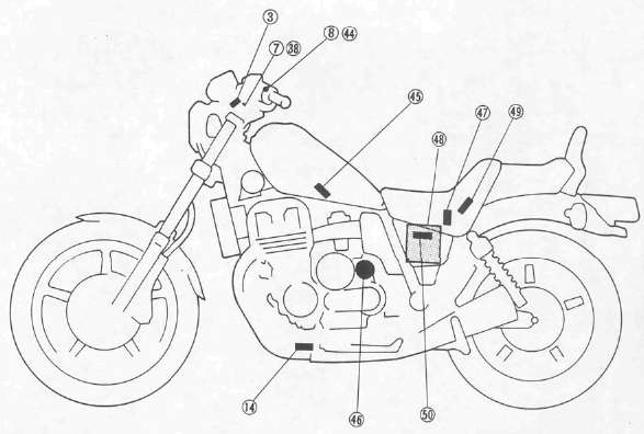
3 Main switch
7 Fuse "IGNITION" (10A)
8 "ENGINE STOP" switch
14 Sidestand switch
39 Fuse "HEAD" (15A)
44 "START" switch
45 Starting circuit cut-off relay (Relay assembly)
46 Starter motor
47 Starter relay
48 Battery
49 Fuse "MAIN" (30A)
50 Diode assembly
STARTING CIRCUIT OPERATION
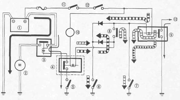
The starting circuit on this model consists of the starter motor, starter relay, starting circuit cutoff relay, and sidestand relay. If the engine stop switch and the main switch are both on, the starter motor can operate only if:
• The transmission is in neutral (the neutral switch is on.)
• The sidestand is up (the sidestand switch is on) and the clutch lever is pulled in (clutch switch is on.)
![]() When the transmission is in neutral.
When the transmission is in neutral.
 When the sidestand is up and the clutch lever is pulled in.
 When the engine is running.
1 Battery
2 Starter motor
3 Starter relay
4 Starting circuit cut-off relay
5 Starter switch
6 Neutral switch
7 Sidestand switch
8 Clutch switch
9 Sidestand relay
10 Tachometer
11 Main switch
12 Engine stop switch
13 To ignitor unit
|
Turn main switch to "ON" and engine stop switch to "RUN" |
|
|
Transmission is |
|
|
▼ |
▼ |
|
In neutral |
In gear |
|
▼ |
▼ |
|
Push starter switch Engine will start |
Raise Sidestand and Pull in clutch lever |
|
▼ |
▼ |
|
Ensure Sidestand is up |
Push starter switch: Engine will start |
|
▼ |
▼ |
|
Motorcycle can be ridden |
|
TROUBLESHOOTING CHART
|
THE STARTER MOTOR DOES NOT OPERATE. |
|
|
|
▼ |
|
|
|
|
||
|
Connect "L/W" lead from the starter relay 1 to the battery negative (-) terminal 2 ; use a jumper lead. |
► |
The engine does not rev smoothly. |
|
▼ |
||
|
Recharge or replace the battery. |
||
|
|
||
|
► |
The engine does not operate. | |
|
▼ |
||
|
▼ |
|
|
|
Check the battery voltage (12V) on the "L/W" lead from the starter relay. |
||
|
The engine operates. |
||
|
▼ |
||
|
▼ |
||
|
Main and engine stop switches are turned to "ON". |
||
|
If the starter relay does not click, check the starter relay and starter motor. |
||
| ▼ | ||
|
|
||
|
|
||
|
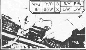
Connect "B/Y" lead to "ground" on the frame; use a jumper lead 1. |
||
|
► |
|
|
|
If the relay unit does not click, check the battery voltage (12V) on the "R/W" lead. |
||
|
|
▼ |
|
|
Check for an open or poor connection between the main switch and relay unit. |
||
|
▼ |
||
|
If the relay unit clicks, check the starter, sidestand, clutch and neutral switches. Replace switch(es) if necessary. |
|
|
STARTING CIRCUIT CUTOFF RELAY (Relay Assembly)
1. Remove:
• Seat
• Fuel tank
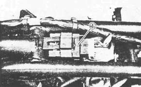
• Relay assembly 1
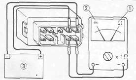
2. Check the relay contacts Use 12V battery 3 and Pocket Tester (90890-03112). Replace relayif out of specification.
Battery Connected: 0Ω 1 Battery Disconnected: ∞ 2
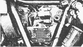
DIODE
1. Remove:
• Left side cover
• Diode 1
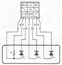
2. Check:
• Diode continuity/discontinuity
Defective element(s) -> Replace the unit.
|
Checking element |
Pocket tester connecting point |
Good |
|
|
(+) (red) |
(-) (black) |
||
|
D1 |
G |
L/W |
O |
|
L/W |
G |
X |
|
|
D2 |
Y |
Sb |
O |
|
Sb |
Y |
X |
|
|
D3 |
W/G |
W |
O |
|
W |
W/G |
X |
|
|
R |
G |
B/R |
8.2Ω |
O: Continuity (0Ω) (Scale Ω x 1k)
x : Discontinuity (∞) (Scale Ω x 1)
NOTE:
The results "o" or "x" should be reversed according to the pocket tester polarity.
NEUTRAL SWITCH

1. Remove:
• Left side cover
• Panel
2. Check the neutral switch contact. Replace if out of specification.
|
Shift pedal 3 |
In neutral |
In gear |
|
Tester |
0Ω |
∞Ω |
1 Blue lead
2 Ground
SIDESTAND SWITCH
1. Refer to neutral switch removal steps.
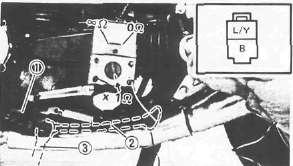
2. Check the sidestand switch 1 contact. Replace switch if out of specification.
|
Sidestand |
Up 2 |
Down 3 |
|
Tester |
0Ω |
∞Ω |
CLUTCH SWITCH
1. Remove headlight unit
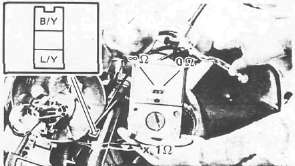
2. Check clutch switch contact. replace if out of specification.
|
Clutch lever |
Pull in |
Not pull in |
|
Tester |
0Ω |
∞Ω |
STARTER SWITCH
1. Remove the headlight unit.

2. Check starter switch contact. Replace if out of specification.
|
Starter switch |
ON |
OFF |
|
Tester |
0Ω |
∞Ω |
STARTER RELAY Inspection
Preparation steps:
• Disconnect starter motor red lead.
• Connect Pocket Tester leads to relay terminals.
•Turn main switch to "ON".
• Turn engine stop switch to "RUN".
• Move shift pedal to "NEUTRAL"

|
Push starter switch to "ON" |
||
|
▼ |
▼ |
|
|
Relay clicks and tester reads 0Ω |
Relay does not click and tester does not read 0 Ω |
|
|
▼ |
▼ |
|
|
OK |
Measure resistance: |
|
|
|
||
|
▼ |
▼ | |
|
Resistance less than 1 Ω |
Resistance more than 1 Ω | |
|
▼ |
▼ | |
|
Check connections |
Replace relay | |
Starter Motor
Starter MotorSTARTER MOTOR
1 O-ring
2 Brush
3 Armature
4 Washer
5 Circlip
Removal
Refer Chapter 3. "ENGINE DISASSEMBLY".
Inspection
1. Inspect commutator outer surface. Clean with 600 grit sandpaper if dirty. Check mica insulation between commutator segments and scrape mica to proper limits. Use a hacksaw blade that is ground to fit.

Mica Undercut 1 : 0.4 - 0.8 mm (0.02 - 0.03 in)
NOTE:
The mica insulation of commutator must be under-cut to ensure proper operation of commutator.

2. Measure the armature coil continuity 1. Replace or rewind starter motorif necessary.
Armature Coil: 0.014Ω ± 6% at 20°C (68° F)
Measure the armature coil insulation 2. Replace the starter motor if shorted.

3. Inspect:
• Front cover bearing 1
• Center and rear covers bushings 2
Replace if damaged.
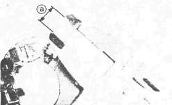
4. Measure the length of each brush length a and replace if less than minimum length.
Minimum Brush Length: 8.5 mm (0.34 in)
5. Check the brush spring pressure and compare with new spring. Replace spring if weak.

