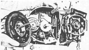
Engine Assembly and Adjustment
Engine Assembly and AdjustmentLower Crankcase
Lower CrankcaseLOWER CRANKCASE

1 Drive axle assembly
2 5 th wheel gear
3 O-ring
4 Housing
5 Shift cam
6 Shift cam locating pin
7 Shift fork 3
8 Shift fork 2
9 Shift fork 1
10 Shift fork guide bar
11 Circlip
12 Dowel pin
13 Blind plug
14 Middle drive gear assembly

1. Install:
• Drive axle assembly 1
• 5th wheel gear 2
• new O-ring 3 onto the housing 4
• Drive axle bearing housing 4
Drive Axle Bearing Housing: 12 Nm (1.2 m kg, 8 .7 ft-lb)

2. Install:
• Shift cam 1
• Shift cam locating pin 2
• Stopper plate 3
• Bolt
• Neutral switch 4
Shift Cam Locating Pin: 8 Nm (0.8 m-kg, 5 .8 ft-lb)
Neutral Switch: 20 Nm (2.0 m-kg, 14 ft-lb)
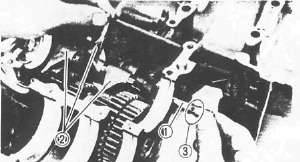
3. Install:
•Shift forks 2
•Guide bar 1
NOTE: • All
shift fork numbers should face the left side and be in sequence (1, 2 ,
3 ), starting from the left.
• The guide bar groove 3 should face the right side.
4. Place the shift cam and transmission gears in NEUTRAL position.
CAUTION:
Be sure the gear shifts correctly while hand-turning the shift cam.
5. Clean the crankcase counterbore where the main bearing is fitted.
6. Install the crankshaft bearings See inspection for crankshaft bearing selection.
CRANKSHAFT
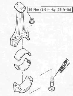
1. Clean:
• Crankshaft
• Connecting rods
2. Install the connecting rod bearings into connecting rod and cap.
3. Lubricate the connecting rod bolt threads with Molybdenum Disulfide Grease
4. Apply engine oil to the crankshaft pins.
5. Install:
• Connecting rods
• Rod caps

NOTE:
• Be sure the letter on both components align to form a perfect character.
• The stamped "Y" mark on the connecting rods 1 should face towards the left side of the crankcase.
Upper Crankcase
Upper CrankcaseUPPER CRANKCASE

1 Crankshaft bearing
2 Drive chain guide
3 Starter idle gear
4 A.C.G. drive chain
5 Oil seal
6 Starter clutch assembly
7 Main axle assembly
8 A.C.G. shaft
9 O-ring
10 Oil spray nozzle
11 Housing
12 Cam chain guide
|
CONNECTING ROD BEARING SELECTION: |
|
|
CALCULATED NO. |
COLOR CODE |
|
1 |
BLUE |
|
2 |
BLACK |
|
3 |
BROWN |
|
4 |
GREEN |

1. Install:
• Crankshaft bearings 1
• Drive chain guide 2
• Starter idle gear 3
Drive Chain Guide: 8 Nm (0.8 m-kg, 5.8 ft-lb)
Starter Idle Gear: 8 Nm (0.8 m-kg, 5.8 ft-lb)
2. Apply engine oil to the bearings.
3. Place the cam chain 1 , drive chain 2 , and oil seal 3 onto the crankshaft.
4. Install the crankshaft (onto the upper crankcase)
NOTE:
• Insert the oil seal flange completely into the crankcase positioning groove.
•Be careful not to damage the oil seal duringinstallation.
• Blind plug 4
• Dowel pins 5
5. Place the drive chain on the starter clutch assembly.
6. Install
• Starter clutch assembly 1 onto the upper crankcase
• A.C.G. shaft
7. Install:
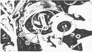
• Oil spray nozzle 1 with new O-ring 2
• Housing with new oil seal 3
NOTE:
Lightly apply grease to the oil seal lips.
Housing Bolt: 10 Nm (1.0 m-kg, 7.2 ft-lb) LOCTITE®

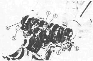
8. Install:
• O-ring (New) 1
• Dowel pins 2
• Half clips 3
• Main axle assembly 4
• Bearing 5
• Middle drive shaft assembly 6
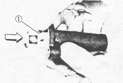
9. Position the bearing pin (left bearing) as shown 7.
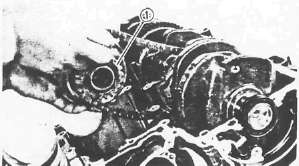
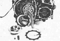
CRANKCASE ASSEMBLY

1. Attach a length of wire to the cam chain.
2. Apply Yamaha bond No. 1215 (908 8 5505).
NOTE:
DO NOT ALLOW any sealant to come in contact with the oil galley O-ring, or crankshaft bearings. Do not apply sealant to within 2-3 mm (0.08-0.12 in) of the bearings.
3. Install the lower crankcase onto the upper crankcase.

• Be sure the shift fork (No. 1 ) 1 engages the groove 2 in the 2nd pinion gear on the main axle.
• Insert the oil seal and blind seal flanges completely into the crankcase positioning grooves.
• Be careful not to damage the seals during installation.
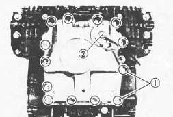
4. Install:
• Bolts
• Washers
• Clamps
• Battery negative lead
5. Tighten:
• Crankcase bolts
Crankcase:
6 mm bolt: 12 Nm (1.2m-kg, 8.7ft-lb)
8 mm bolt: 24 Nm(2.4m-kg, 17 ft-lb)
NOTE:
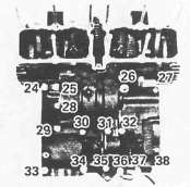
The embossed numbers in the crankcase designate the crankcase tightening sequence.

LOWER CRANKCASE
UPPER CRANKCASE
Oil Pump, Clutch and Water Pump
Oil Pump, Clutch and Water PumpOIL PUMP AND OIL PAN

1 Chain cover
2 Oil pump sprocket
3 Oil pump drive sprocket
4 Oil pump cover
5 Inner rotor
6 Spring
7 Relief valve
8 Shaft
9 Dowel pin
10 Outer rotor
11 Dowel pin
12 O-ring

1. Install:
• O-ring 1 onto the oil pump assembly
• Chain
• Oil pump assembly
• Chain cover
Oil Pump: 12 Nm (1.2 m-kg, 8.7 ft-lb)
2. Install:
• Oil pan
• Wire clamps 1
• Bolts
• Oil level switch 2
Oil Pan: 12 Nm (1.2 mkg, .7 ft-lb)
Oil Level Switch: 8 Nm (0.8m-kg, 5.8 ft-lb)
CLUTCH

1 Plate washer
2 Oil seal
3 Bearing
4 Pinion gear
5 Plate washer
6 Circlip
7 Lock washer
8 Friction plate
9 Clutch plate
10 Wire clip
11 Clutch plate
12 Clutch boss spring
13 Spring seat
14 Thrust plate
15 Spacer
16 Bearing (15-28)
17 Oil pump drive sprocket
18 Collar
19 Thrust plate
20 Pull rod
21 Bearing
22 Water pump drive shaft
23 Spacer
24 Water pump drive gear
Note:
The outermost friction plate has a V-cut in it. Give some identifying mark to the corresponding dog in the clutch housing.
CLUTCH AND OIL PUMP DRIVE SPROCKET
1. Install:
• Thrust plate 1
• Oil pump drive sprocket 2
12 Nm (1.2m-kg, 8.7 ft-lb)
2. Hook the drive chain on the drive sprocket.
3 Install:
• Collar 3
4. Install:
• Water pump drive shaft 1
• Clutch housing
CAUTION:
Be sure that the oil pump drive gear tabs engage the clutch housing grooves on its back or the tabs will be damaged when tightening the clutch boss securing nut.

5. Install:
• Bearing 1
• Spacer 2
• Thrust plate 3
• Clutch boss 4
• Lock washer (New) 5
• Nut 6
Clutch Boss: 70 Nm (7.0 m kg, 50 ft lb)
6. Bend lock washer tabs against the nut flats.
7. Install:
• Friction plates
• Clutch plates

8. Install:
• Friction plate (with V-cut 1 in tab)
NOTE:
Install the friction plate so that the V-cut tab is in the identified dog 2 . If you forget to identify the position with a mark, measure the width of each dog. 13.8 mm (0.543 in) width is for that position. The other width are 14 mm (0.551 in).

9. Install:
• Plate washer 2
• Thrust bearing 3 onto the pull rod 4
• Pull rod 4 into the pressure plate 1
10. Install:
• Pressure plate
NOTE:
Align a dot on the clutch boss with a dot on the pressure plate.
• Clutch springs
Clutch Spring: 8 Nm (0.8 m-kg, 5.8 ft-lb)
11. Install:
• Oil baffle plate
• Dowel pins
• Gasket
• Clutch cover

NOTE:
Set the gear of the clutch pull rod facing approximately 45° from horizontal toward the rear.

• Set the clutch lever 1 on the right crankcase cover parallel to the gasket surface.
• Make sure that the punch mark on the lever 2 align with the mark on the crankcase cover 3 when pushing the lever towards the front by hand.
Clutch Cover: 1 2 Nm(1.2m-kg,8.7ft-lb)

12. Install:
• Spacer 1
• Water pump drive gear 2
• Water pump drive gear cover.
Water Pump Drive Gear: 12 Nm (1.2 m-kg, 8.7 ft-lb) LOCTITE®
Cover: 8Nm(0.8m-kg, 5.8ft-lb)
Middle Gear, Generator, Starter and Pickup Coil
Middle Gear, Generator, Starter and Pickup CoilMIDDLE GEAR
1. Install:
• Bearing retainers 1
• TORX screws (New)
• Oil level maintaining plug
Bearing Retainer: 25 Nm (2.5 m-kg, 18 ft-lb)
2. Stake the screw heads to the dents on the bearing retainers with a center punch.

3. Install:
• Shims 1
• Middle driven gear housing 2
• Bolt
Middle Driven Gear Housing: 25 Nm (2.5 m-kg, 18 ft-lb). Use LOCTITE®
SHIFTER

1. Install:
• Washer 1
• Shift shaft 2
• Shift lever3
• Oil level maintaining plug 4
• Gasket

2. Install:
• Crankcase cover
• Wire harness clip 1
• Bolts
Crankcase Cover: 12 Nm (1.2 m-kg, 8.4 ftlb)
GENERATOR AND STARTER

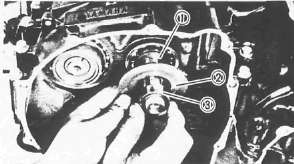
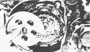
1. Install:
• Rotor Use Rotor Holding Tool (90890-04043) 1 .
Rotor: 55 Nm (5.5 m-kg, 40 ft-lb)
2. Install the stator coil 1
NOTE:
Align the grooves on the stator coil core with the bolt holes on the crankcase.
• Gasket 2
• A.C.G. cover
A.C.G. Cover: 12 Nm (1.2 mkg, 8 .4 ft-lb)

3. Install:
• Starter motor
• Bolts
Starter Motor: 7 Nm (0.7m-kg, 5 .1 ft-lb)
NOTE:
• Be careful the O-ring 1 is not damaged when installing the starter motor.
• Route the A.C.G. lead wires 2 as shown.
PICKUP COIL

1. Install:
• Pickup coil assembly
• Timing plate
NOTE: Align the locating pin on the crankshaft with the corresponding slot in the timing plate.
Pickup Bolt: 8 Nm (0.8 m-kg, 5.8 ft-lb)
Timing Plate: 24 Nm (2.4 m-kg, 17 ft-lb)
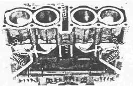
Pistons and Cylinder
Pistons and CylinderPISTON AND CYLINDER
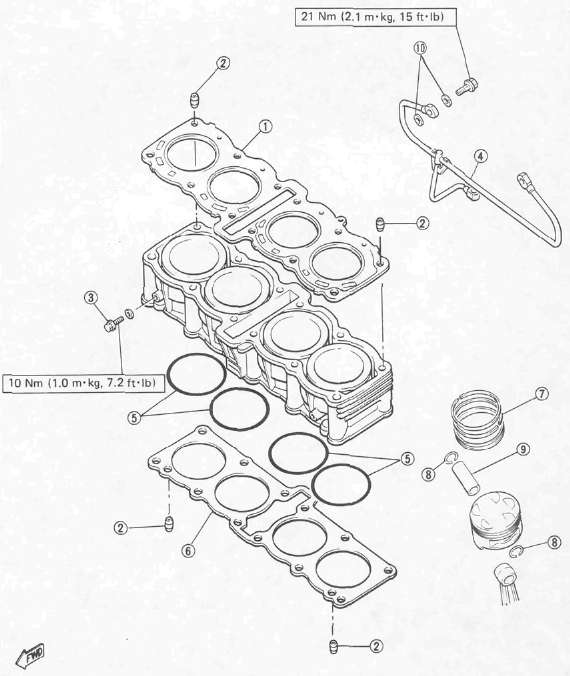
1 Cylinder head gasket
2 Dowel pin
3 Drain bolt
4 Oil delivery pipe
5 O-ring
6 Cylinder base gasket
7 Piston ring
8 Piston pin clip
9 Piston pin
10 Copper washer
1. Install:
• Piston rings (onto the pistons)
NOTE:
Be sure to install the rings so that Manufacturer's marks or numbers are located on the top side of the rings. Oil the pistons and rings liberally.
2. Install pistons.

NOTE:
• Be sure the piston is positioned correctly.
• Always install new piston pin clips 1
• The "EX" mark 2 on the piston should face toward the front (Exhaust side).
3. Oil liberally:
• Pistons
• Rings
• Cylinders
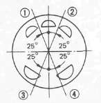
4. Set piston ring ends as per the above diagram.
CAUTION:
Make sure the ends of the oil ring expanders do not overlap.
1 TOP
2 OIL RING (LOWER RAIL)
3 OIL RING (UPPER RAIL)
4 2ND

5. Install:
• Cam chain guide (Rear) 1
Cam Chain Guide (Rear): 10 Nm (1.0m-kg, 7.2ft-lb)
6. Check guide movement. Reassemble if the action is not smooth.
7. Install:
• Dowel pins
• Gasket (New)
• Cylinder
CAUTION:
• Be careful not to damage the cam chain guide during installation.
• Pass the cam chain through the cam chain cavity.

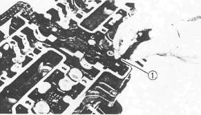
8. Position oil delivery pipe 1
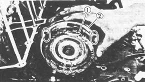
9. Set the dial gauge on the No. 1 piston head center as shown to find the No. 1 piston top dead center and check whether the "T" mark on the timing plate and stationary pointer are aligned or not. If not, loosen the pointer securing screw and adjust.
Cylinder Head
Cylinder HeadCYLINDER HEAD

1 Check bolt
2 Dowel pin
3 Camshaft case gasket
4 Valve guide
5 O-ring
6 Camshaft case
7 Cylinder head
8 Oil pipe
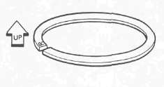
[A] Be sure the "UP" mark faces upward.

1. Install:
• Dowel pins 1
• Cylinder head gasket (New)
• Cylinder head
NOTE:
• Be careful not to damage the cam chain guide during installation.
• Pass the cam chain through the cam chain cavity.

2. Tighten nuts in sequence as shown and torque the nut in two stages.
Cylinder Head: [10 mm ] 37 Nm (3.7 m-kg, 27 ft-lb)
3. Install the cam chain guide (Front) 1
NOTE:
The lower end of chain guide must rest in the cam chain guide slot in the crankcase.
Camshafts
CamshaftsCAMSHAFT

1 Cam cap
2 Dowel pin
3 Cam chain sprocket (IN)
4 Cam chain sprocket (EX)
5 Camshaft (IN)
6 Camshaft (EX)
7 Lifter
8 Adjusting pad
9 Cam chain guide (Front)
10 Oil delivery pipe
11 Copper washer
12 Camchain tensioner
13 Camchain tensioner end cap bolt
14 Camchain guide (Upper)
15 Valve retainer
16 Spring seat
17 Valve spring
18 Spring seat
19 Oil seal
20 Valve

* When installing the sprocket, use holes except for the one with a punch mark.
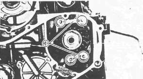
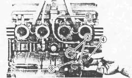
Camshaft installing steps:
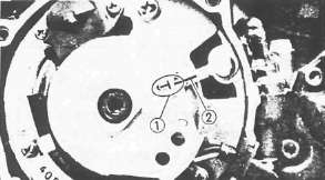
• Align the "T" mark on the timing plate 1 with the stationary pointer 2 . Do not turn the crankshaft during the camshafts installation.
• Install the cam chain sprockets onto the camshafts.
• Apply engine oil to the camshaft bearing surface.

• Turn the camshafts by hand so that the timing marks 3 (o: small hole) on the camshafts face upward.
• Install the dowel pins into the cam caps.
• Install the caps (without IN3 and EX3) onto the camshafts and tighten the cap bolts.
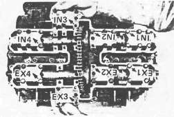
NOTE:
• The arrow mark on the caps should face toward the outside.
• The numbers are punched on the camshaft caps in increments from left to right.
Cam Cap: 10 Nm (1.0m-kg, 7.2 ft-lb)

2. Install cam chain sprockets
Cam chain sprockets installing steps:
• Align the "T" mark on the timing plate 1 with the stationary pointer on the pickup coil 2 . Do not turn the crankshaft when installing the sprockets.
• Place the cam chain onto the exhaust sprocket.

• Install the sprockets and finger tighten the sprocket bolts 3
NOTE:
When installing the sprocket, use holes except for the one with a punch mark 4.

• Rotate the exhaust camshaft to align the punched mark on the camshaft 5 with the "—" mark on the EX2 cam cap 6
• Force the exhaust camshaft clockwise to remove the cam chain slack.
• Place the cam chain onto the intake sprocket.
• Install the sprocket and finger tighten the sprocket bolt.

• Rotate the intake camshaft to align the punched mark on the camshaft with the "—" mark on the IN2 cam cap.
• Force the intake camshaft clockwise to remove all the cam chain slack.
• Insert your finger into the cam chain tensioner hole, and push the cam chain guide inward 7.
•While pushing the cam chain guide, be sure camshaft timing marks align with the cap marks.
• Remove the intake sprocket if marks do not align.
• Change the meshing position of sprocket and cam chain.
3. Install the cam chain tensioner
Cam chain tensioner installation steps:
• Remove the tensioner end cap bolt and spring.
• Release the cam chain tensioner one-way cam 1 and push the tensioner rod into the tensioner body.
• Install the tensioner with a new gasket onto the cylinder.
Tensioner Body: 10Nm(1.0m-kg, 7.2ft-lb)

• Install the tensioner springs and end cap bolt 1 . Tighten the bolt.
Tensioner End Cap Bolt: 9 Nm (0.9m-kg, 6.5 ft-lb)
• Turn the crankshaft and install the sprocket securing bolts.
• Tighten the sprocket bolts.
Sprocket: 20 Nm (2.0m-kg, 14ft-lb)
CAUTION:
Be sure to attain the specified torque value to avoid the possibility of these bolts coming loose and causing damage to the engine.
Install the caps (IN3 and EX3) and camchain guide (Upper).
4. Apply engine oil to the cam chain, sprockets, camshafts, and valves.
5. Turn the crankshaft counterclockwise a few turns to ensure that it turns smoothly.
CAUTION:
Be sure the exhaust and intake camshaft mark are aligned with the cam cap marks.

6. Measure:
Valve clearance
Out of specification -> Adjust.
IN: 0.11 -0.20 mm (0.004 ~ 0.008 in)
EX: 0.21 -0.30 mm (0.008-0.012 in)
7. Install:
• Cylinder head cover
• Bolts
• Spark plugs
Cylinder Head Cover: 10 Nm (1.0m-kg, 7.2fMb)
SparkPlug: 17 .5 Nm (1.75 m-kg, 12 .5 ftlb)
8. Install:
• Gasket
• Crankshaft end cover (Left)
• Screw
Crankshaft End Cover (Left): 7 Nm (0.7 m-kg, 5.1 ft-lb)
Radiator Pipes, Carburettor Joints and Oil Delivery Pipe
Radiator Pipes, Carburettor Joints and Oil Delivery PipeRADIATOR PIPES, CARBURETOR JOINT, AND OIL DELIVERY PIPE

1. Install:
• Union bolt with copper washer 1
• Cylinder head side cover 2
Oil Delivery Pipe: 21 Nm (2.1 m-kg, 15 ft-lb)

2. Install:
• Carburetor joints 1
• Radiator pipes (with O-ring 2 ) 3
Carburetor Joint: 12 Nm (12 m-kg, 8 .7 ft-lb)
3. Install:
• Bypass hose 1
• O-rings 2
• Radiator pipe 3
• Water purnp joint 4
Water Pump Joint: 10 Nm (1.0 m-kg, 7.2 ft-lb)
4. Install:
• Radiator pipe 1
• Cover (Right) 2
Radiator Pipe: 8Nm (0.8m-kg, 5.8ft-lb)
Cover: 8 Nm (0.8m-kg, 5.8 ft-lb)
• Drain bolts 3