Chassis Maintenance
Chassis MaintenanceFinal Gear Oil and Air Filter
Final Gear Oil and Air Filter
(1) Oil
FINAL GEAR OIL Oil Level Measurement
1. Place the motorcycle on a level area and place on its centerstand.
2. Remove the oil filler cap
3. Observe the oil level (2) and add oil if necessary.
NOTE:
Oil level must be up to the brim of the filler hole.
CAUTION:
Be sure that no foreign material enters the final gear case.

Gear Oil Replacement
1. Place a receptacle under the final gear case.
WARNING:
Spilling oil on the tires or on the ground under the tires will reduce traction and may result in an accident. Use a funnel, stiff piece of card, plastic or similar to ensure all oil is directed into the receptacle.
2. Remove the filler cap and drain plug (1). Drain final gear oil into the receptacle.
3. Re-install the drain plug. Torque to 23 Nm (2.3 m-kg, 17 ft-lb).
4. Fill the gear case to the specified level.
Final Gear Oil: SAE 80 API "GL-4" Hypoid gear oil
Oil Capacity: 0.20 L (0.18 Imp qt, 0.21 US qt)
NOTE:.
If desired, an SAE 80W90 Hypoid gear oil may be used for all conditions.
5. Install the filler cap. Torque cap to 23 Nm (2.3 m-kg, 17 ft-lb)
AIR FILTER
1. Remove the seat, fuel tank and rubber cover.

2. Remove the air filter cover (1)

3. Eliminate dust using compressed air.
Note:
Blow out dust from the inside out.
4. Inspect the element and replace if damaged.
CAUTION:
The engine should never be run without the air/filter element installed; excessive piston and/or cylinder wear may result.
5. Install the element back in the airbox. Installation steps are the reverse of removal.
CAUTION:
Make sure the element cover fits into the corresponding filter case edge.
Brakes
BrakesFRONT BRAKE
Brake Fluid Inspection
1. Check the Brake fluid level. Replenish as required.
NOTE:
Use only DOT 3 or equivalent fluid from a sealed container.
WARNING:
Be sure that:
•Water does not enter the master cylinder when refilling.
•Spilled fluid is cleaned up immediately to prevent painted surfaces or plastic parts from eroding.

(1) Lower level

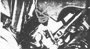
Front Brake Lever Free Play Adjustment
1. Loosen the adjuster locknut (1)
2. Adjust the free play (a) by turning the adjuster (2) until the free play (a) is within the specified limits.
Brake Lever Free Play (a): 2- 5 mm (0.08- 0.20 in)
CAUTION:
Proper lever free play is essential to avoid excessive brake drag.
3. Tighten the adjuster locknut

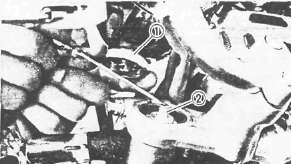
Brake Pad Inspection
1. Activate the brake lever.
2. Inspect the wear indicator (1). If the indicator almost contacts disc (2), replace pads. Refer to "CHASSIS."
REAR BRAKE
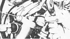
Rear Brake Pedal Height Adjustment

1. Loosen the adjuster locknuts (1)
2. Adjust the brake pedal height (a) by turning the adjuster (2) until the brake pedal position is at the specified height.
Brake Pedal Height (a): 10 mm (0.4 in) Below the Top of the Footrest
WARNING:
Adjust pedal height, then adjust brake pedal free play.

(1) Wear limit line
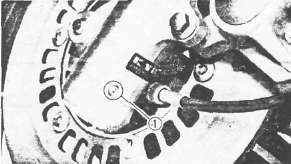
Rear Brake Shoe Inspection
1. Depress brake pedal.
2. Inspect the wear indicator (2). if the indicator is at wear limit line (1), replace brake shoes.

Rear Brake Pedal Free Play Adjustment
1. Rotate the adjuster nut (1). Turn it clockwise or counterclockwise until proper brake pedal free play is attained.
Brake Pedal Free Play: 20-30 mm (0.8-1.2 in)
WARNING:
Check to verify correct brake light operation after adjustment.
Brake Light Switch Adjustment
1. Hold the switch body (1) with your hand so that it does not rotate and turn the adjusting nut (2) .
Cable inspection and lubrication
Cable inspection and lubricationCable inspection and lubrication steps:
• Remove the two screws that secure throttle housing to handlebar.
• Hold cable end high and apply several drops of lubricant to cable.
• Coat metal surface of disassembled throttle twist grip with suitable all-purpose grease to minimize friction.
•Check for damage to cable insulation. Replace any corroded or obstructed cables.
• Lubricate any cables that do not operate smoothly.
Yamaha Chain and Cable Lube or SAE 10W30 Motor Oil
BRAKE AND SHIFT PEDALS/ BRAKE AND CLUTCH LEVERS
Lubricate pivoting parts of each lever and pedal.
Yamaha Chain and Cable Lube or SAE 10W30 Motor Oil
CENTERSTAND AND SIDESTAND
Lubricate centerstand and sidestand at their pivot points.
Yamaha Chain and Cable Lube or SAE 10W30 Motor Oil
Suspension Adjustments and Oil Change
Suspension Adjustments and Oil ChangeFRONT FORK OIL CHANGE
WARNING:
Securely support the motorcycle so there is no danger of it falling over.
1. Place a suitable stand under the engine to raise the front wheel off the ground.
2. Remove the air valve cap (1)
NOTE:
Keep the valve (2) open by pressing it for several seconds so that the air can be let out of the inner tube.
3. Loosen the inner tube pinch bolt (1)
4. Remove the cap bolt (2)
5. Remove the drain screw (1). Drain the fork oil.
WARNING:
Do not allow any oil to contact the disc brake components. If oil is discovered, be sure to remove it, otherwise diminished braking capacity and damage to the rubber components of the brake assembly will occur.
6. Inspect:

•O-ring (1) (Cap-bolt)
•Gasket (Drain bolt screw)
Replace if worn or damaged.
7. Install the drain screw
8. Fill the front forks.
Each Fork:
389 cm3 (13.7 Imp oz, 13.2 US oz)
After filling purnp the forks slowly up and down to distribute the oil.
9. Tighten the cap-bolt and pinch bolt
Cap Bolt: 23 Nm (2.3m.kg, 17 ft-lb)
Pinch Bolt: 20 Nm (2.0 m-kg, 14 ft-lb)
10. Pressurize Fork with specified amount of air. Refer to "Front fork adjustment".
11. Install the fork cap
Maximum Air Pressure: 118 kPa (1.2 kg/,cm 17.1 psi) Do not exceed this amount.
FRONT FORK ADJUSTMENT
1. Place motorcycle on centerstand, then elevate front wheel.
NOTE:
Be sure there is no weight on the front end of the motorcycle and the fork tube is at room temperature when air pressure is checked and adjusted.
2. Remove the fork cap
3. Measure the air pressure with an air gauge and adjust as needed.
NOTE:
Increased air pressure causes stiffer suspension; decreased pressure causes softer suspension.
CAUTION:
Do not use a high pressure air supply that will overpressurize the forks faster than the operator can control. Use only a manual pump or low pressure supply to avoid seal damage.
|
Air Pressure Adjustment |
|
|
To increase air pressure |
Use manual air pump or pressurized air supply. |
|
To decrease air pressure |
Release air by pushing valve pin. |

Standard Air Pressure: 39.2 kPa (0.4 kg/cm3, 5.7 psi)
Maximum Air Pressure: 118 kPa (1.2 kg/cm2, 17.1 psi)
Minimum Air Pressure: Zero
4. Install the Fork cap
REAR SHOCK ABSORBER ADJUSTMENT
If the spring seat is raised, the spring becomes stiffer, and if lowered, it becomes softer.

Standard Position: A A. - Softest E. - Stiffest
WARNING:
Always adjust each shock absorber to the same setting. Uneven adjustment can cause poor handling and loss of stability.
Steering Head Adjustment
Steering Head AdjustmentSteering Head Inspection
1. Place the motorcycle on its centerstand, then elevate the front wheel.
2. Check the steering assembly bearings. Grasp the bottom of the forks and gently rock the fork assembly back and forth. Adjust if any looseness can be detected.
Adjustment

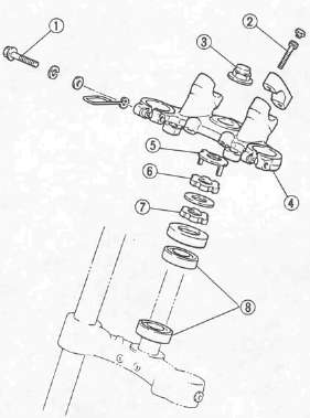
Steering head adjustment steps:
• Loosen the pinch bolts (1) .
• Remove the handlebar securing bolts (2) .
• Remove the handlebar.
•Remove the steering stem nut (3) .
•Remove the steering crown (4) .
•Remove the lock washer (5).
•Loosen the upper ring nut (6) .
•Tighten the lower ring nut (7)
Ring Nut (Lower): 50 Nm (5.0 m.kg, 36 ft-lb)
NOTE:
The tapered side of ring nuts must face downward.
• Loosen the ring nut (7) completely and retighten it to specification.
Rint Nut (Lower): 6Nm (0.6 m-kg, 4.3 ft-lb)
• Check the steering stem by turning it lock to lock. If there is any binding, remove the steering bearings (8) .
(See CHAPTER 6, STEERING HEAD for more details.)
• Hand-tighten the upper ring nut (6) , then align the slots of both ring nuts. If not aligned, hold the lower ring nut (7) and tighten the other until they are aligned.
• Install the lock washer (5).
NOTE:
Make sure the lock washer tab is placed in the slots.
• Install the steering crown (4) and tighten the steering stem nut (3) to specification.
Steering Stem Nut: 110 Nm (11.0 m-kg, 80 ft-lb)
• Install the handlebar (3) and torque the bolt (2) to specification.
Pinch Bolt: 20 Nm (2.0m.kg, 14 ft-lb)
Handlebar Bolt: 20 Nm (2.0 m-kg, 14 ft-lb)

• Install the fork and bolt caps.
Wheels, Bearings and Tires
Wheels, Bearings and TiresFront Wheel Bearings
1. Raise the front end of the motorcycle, and spin the wheel by hand. Touch the axle or front fork white spinning the wheel. Replace the bearings if any vibration is detected.
Note:
It may be necessary to retract the brake pads from the disk in order to freely rotate the wheel.
Rear Wheel Bearings
1. Remove the rear wheel

2. Check the bearing movement by rotating it with the fingers. Replace if any roughness or wear is detected.
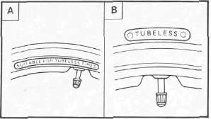
TUBELESS TIRES AND ALUMINUM WHEELS
WARNING:
Always inspect aluminum wheels before a ride.
Do not attempt any repairs to the wheel; replace any defective wheel.
Do not attempt to use tubeless tires on a wheel designed for use with tube-type tire only. Tire failure and subsequent personal injury may result from sudden deflation.
|
A | Wheel |
B Tire |
|
Tube type |
Tube type only |
|
Tubeless |
Tube type or tubeless |
• Be sure to install the proper tube when using tube-type tires.
• New tires have a relatively poor adhesion on the road surface so do not allow them to be subjected to high speed load from maximum speed until after a break-in run of approx. 100 km (60 mi).
• Always use the correct tire inflation pressure according to the operating conditions.

(C) Tubeless tire
(D) Tube type tire
(1) Air valve
(2) Aluminum wheel {Tubeless type)
(3) Tube
(4) Aluminum wheel (Tube type)
Always perform the following steps to ensure safe operation, maximum tire performance and long service.
1. Measure the tire pressure and adjust as necessary.
|
Basic weight: With oil and full fuel tank |
232 kg (511 lb) |
|
|
Maximum load-*- |
238 kg (525 lb) load |
|
|
Cold tire pressure |
Front |
Rear |
|
Up to 90 kg (198 1b) load* |
177 kPa (1.8 kg/cm2, 26 psi) |
196 kPa (2.0 kg/cm2, 28 psi) |
|
90 kg (198 1b) load ~ 238 kg (525 lb) |
196kPa (2.0 kg/cm2, 28 psi) |
275 kPa (2.8 kg/cm2, 40 psi) |
|
High speed riding |
206 kPa (2.1 kg/cm2, 30 psi) |
226 kPa (2.3 kg/cm2, 32 psi) |
* Load is the total weight of cargo, rider, passenger, and accessories.
2. Inspect the tire surfaces for wear or damage. Replace as required.
Minimum Tire Tread Depth: (Front and Rear) 1.0 mm (0.04 in)

(1) Tread depth
(2) Side wall
(3) Wear indicator
3. Inspect the aluminium wheels for damage or cracks. Never attempt even small repairs to the wheel.
NOTE:
Always balance the wheel when a tire or wheel has been changed or replaced.
WARNING:
Ride conservatively after installing a tire to allow it to seat itself properly on the rim.