Engine Disassembly
Engine DisassemblyCylinder Head Removal
Cylinder Head RemovalRADIATOR PIPES, CARBURETOR JOINT, AND OIL DELIVERY PIPE
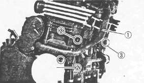
1. Remove:
• Radiator pipe 1
• Cover (Right) 2
2. Drain the coolant (in the cylinder) by removing drain bolts 3
3. Remove;
• Water pump joint 1
• Radiator pipes 2
• Carburetor joints
• Bypass hose 3

4. Remove:
• Oil delivery pipe union bolts 1
• Copper washers
• Cylinder head side covers 2
5. Loosen the cam chain tensioner end plug 3
6. Remove the cam chain tensioner assembly 4

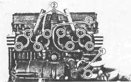
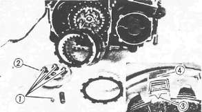
CYLINDER HEAD AND CYLINDER
1. Remove the cylinder head cover
NOTE:
Piston and cylinder can be removed, when necessary, without removing the camshaft.

The main steps are as follows.
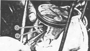
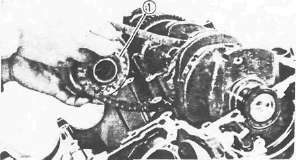
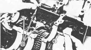
• Disconnect the cam chain using Cam Chain Cutter 1 (90890-01112).

• Remove the cylinder head nuts in the camshaft case using Hexagon Wrench 2 .
• Remove the cam shaft, cam shaft case and cylinder head as assembly.
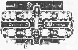
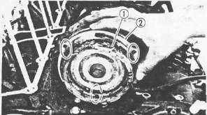
2. Remove:
• Cam chain guide (Upper) 1
• Camshaft cap (I3) 2
• Camshaft cap (E3) 3
• Dowel pins

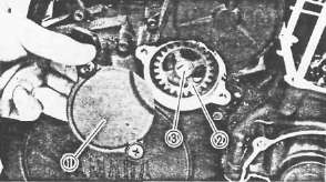
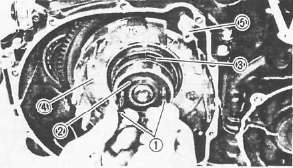
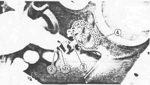
3. Remove:
• Cam chain sprocket bolts 1 Use 2 2 mm (0.88 in) wrench to hold camshaft.
• Camshaft caps (I1, I2, I4, E1,E2, E4)
• Dowel pins
• Camshafts
• Cam chain guide (Front) 1
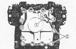
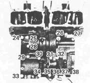
4. Remove:
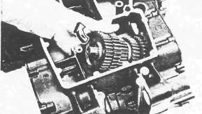
• Cylinder head nut
• Cylinder head
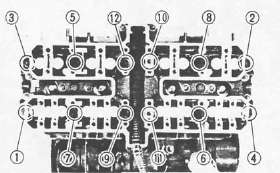
NOTE:
Follow the numerical order shown in photo, start by loosening each nut 1 /4 turn until all are loose.

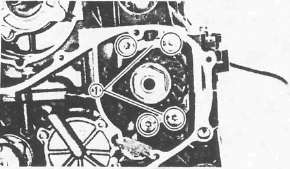
5. Remove:
• Cylinder head gasket 1
• Dowel pins 2
• Cylinder
• Oil delivery pipes 3
• Cylinder base gasket
• Dowel pins
Pistons, Starter, Generator and Pickup Coil
Pistons, Starter, Generator and Pickup CoilPISTON AND CAM CHAIN GUIDE
Mark each piston so it can be reinstalled in the appropriate cylinder.
1. Remove:
• Piston pin clips 1
• Piston pins 2
NOTE: Before removing the piston pin clip, cover the crankcase with a clean rag so you will not accidentally drop the clip into the crankcase.

• Pistons
• Cam chain guide (Rear) 3
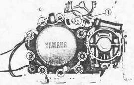
STARTER MOTOR AND GENERATOR

1. Remove:
• Starter motor bolts
• Starter motor assembly 1
• Generator cover 2
2. Remove:
• Stator coil 1
• Gasket 2

3. Attach the rotor Holding Tool (90890-04043) 1
4. Remove the rotor holding bolt 2

5. Attach:
• Rotor Puller Adapter (90890-04052) 1
• Rotor Puller (90890-01080) 2
6. Remove the rotor 3
PICKUP COIL

1. Disconnect:
• Oil level switch lead 1
• Neutral switch lead 2
• Pickup coil lead (from clamps 3 )

2. Remove:
• Timing plate 1
• Dowel pin 2
• Pickup coil assembly 3
Clutch and Oil Pump
Clutch and Oil PumpCLUTCH
1. Remove:
• Water pump drive sprocket cover 1
• Water pump drive sprocket 2
Note:
Water pump drive sprocket bolts 3 is locked with LOCTITE®.
• Spacer
2. Remove:
• Bearing retaining washer 1
• Clutch cover
• Gasket
• Dowel pins
3. Remove:
• Clutch spring bolts 1
• Clutch springs
• Pressure plate 2
• Friction plates
• Clutch plates
NOTE:
The outermost friction plate has a tab with a V-cut 3 in it. Give some identifying mark to the corresponding dog 4 in the clutch housing. This dog is narrowest.

4. Bend the lock washer tab 1
5. Attach the universal Clutch Holder (90890-04086) 2

6. Remove:
• Clutch boss nut 1
• Lock washer 2
• Clutch boss 3
• Thrust washer 4
• Oil baffle plate 5
7. Install:
• Clutch cover bolts 1 (into clutch housing spacer holes)
8. Remove:
• Clutch housing spacer 2
• Bearing 3
• Clutch housing 4
• Water pump drive shaft 5
OIL PUMP
1. Remove:
• Oil filter
• Oil level switch 1
• Oil pan
• Clamps 2
• Gasket
• Dowel pins

2. Remove:
• Oil pump drive chain cover 1
• Oil pump assembly 2

3. Remove:
• Oil pump drive sprocket 1
• Chain 2
• Collar 3
• Thrust plate 4
Shifter, Middle Gear and Crankcase
Shifter, Middle Gear and CrankcaseSHIFTER AND MIDDLE GEAR

1. Remove:
• Crankcase cover (Left) 1
• Gasket
• Dowel pin 2
• Shift shaft 3
• Shift lever 4
• Oil level maintaining plug 5

2. Remove:
• Middle driven gear housing 1
• Shims 2
3. Remove:
• Bearing retainer 1 Use Torx Driver #40 (90890-04049).
CRANKCASE
1. Remove:
• Bolts (Crankcase)
• Clamps
• Battery negative lead
NOTE:
• Remove the bolts starting with the highest numbered one.
• The embossed numbers in the crankcase designate the crankcase tightening sequence.
Upper crankcase

Lower crankcase
2. Remove:
• Lower crankcase
• Blind plug (from crankcase right end)
• Crankshaft bearings
NOTE:
Identify each crankshaft bearing position very carefully so that it can be reinstalled in its original place.
Gears, Starter Drive and Shift Drum
Gears, Starter Drive and Shift DrumMAIN AXLE AND MIDDLE DRIVE GEAR

1. Remove:
• Middle drive gear 1
• Main axle 2
• Bearing 3
• Dowel pins 4
• O-ring 5
A.C.G. SHAFT, STARTER DRIVE, AND CRANKSHAFT

1. Remove housing using Torx Driver #30 (90890-05245)

2. Remove:
• Oil spray nozzle 1
• A.C.G. shaft 2
Use Armature Shock Puller (90890-01290) and (90890-01291)3
3. Remove:
• Starter clutch assembly 1
• Crankshaft
5. Bend the lock washer tab 1
6. Remove:
• Starter idle gear shaft bolt 2
• Lock washer
• Stopper plate
• Starter idle gear shaft 3
• Starter idle gear 4
SHIFT CAM AND DRIVE AXLE
1. Remove:
• Guide bar 1
• Shift forks 2

2. Remove:
• Neutral switch 1
• Bolts 2
• Stopper plate 3
• Shift cam locating pin 4
• Shift cam 5

3. Remove:
• Drive axle bearing cover 1
• 5th wheel gear 2
4. Remove the drive axle assembly