This series assumes you took the carbs apart, and are trying to figure out how to put them back together again. If you haven’t taken them apart yet, it’s a good idea to skim through this first anyway. Address any questions to: xj-owners@micapeak.com, and we’ll try to talk you through it.
Pictures and text by Dwayne Verhey
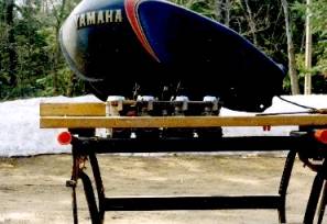
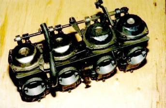
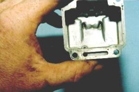
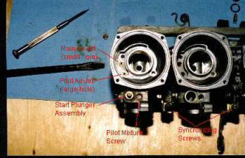
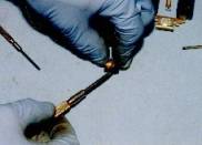
The “Before” picture. Note the arrangement of the starter circuit shaft and levers.
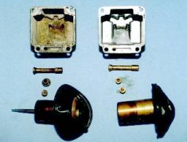
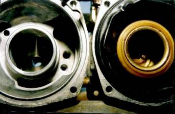
Before and after cleaning. The parts on the left are as removed. This carburetor was last cleaned 2 or 3 years ago, and was stored full of gas with stabilizer added for each winter, and run for 20 minutes every 2 or 3 weeks. Even so, there’s obviously lots of varnish!
The parts on the right were soaked in a commercial carburetor cleaner (KleenFlo) overnight. The piston was soaked upright so the rubber diaphragm was not immersed. Don’t soak any rubber bits, they swell up and soften, and may be ruined.
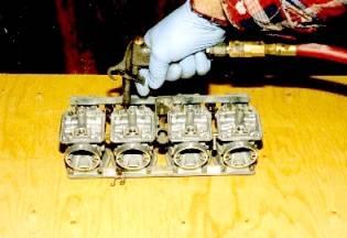
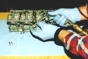
All passages should be thoroughly blown out with compressed air while the parts are still wet with cleaner. Then they should be rinsed (water or mineral spirits, depending on the directions of the cleaner) and blown out again.
Don’t forget the starter jet and passage, located in the float bowl. The jet is tiny (the same size hole as the pilot jet); so don’t be tempted to shove something down there to open it up! If absolutely necessary to clear a completely plugged jet, use a bristle from a stiff nylon brush. Then soak it out in cleaner overnight again.
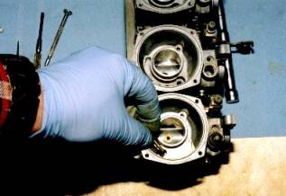
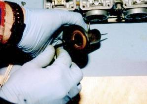
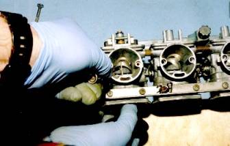
Many passages are joined. Place a finger over each passage outlet, one at a time, to ensure they are all clear. The same applies with the emulsion tube, shown here. Gloves not only keep your hands clean, they protect your hands from the harsh chemicals, and the possibility of an air embolism when working with compressed air. Blue nitrile gloves seem to work best.
(SWMBO wants to know how I managed to work the camera for this shot. Trade secret ;-)
All parts should be inspected before re-assembly. This piston and diaphragm are no longer serviceable. The plastic retainer has cracked and separated. A new one was obtained from a set of parts carbs from a wreckers.
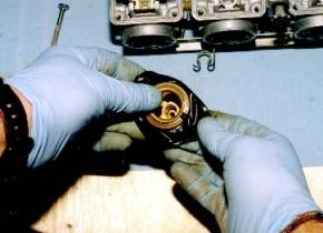
Note the fine, fragile, screen attached to the float seat. Careful when blowing this out. The screen may become dislodged and fly across the room! (Don’t ask me how I know this…)
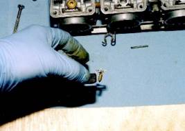
Here’s all the little fiddly bits laid out and identified. Pay particular attention to the pilot screw bits. There’s a tiny spring, washer and o-ring that are easily lost, and may not want to come out of the hole until you start blowing things out with compressed air.
Guess which side of the garage they’ll land on?
You’re better off gently picking them out with a dental probe, toothpick, or tiny screwdriver during the disassembly. They’re much easier to find that way…
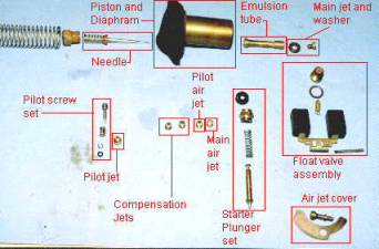
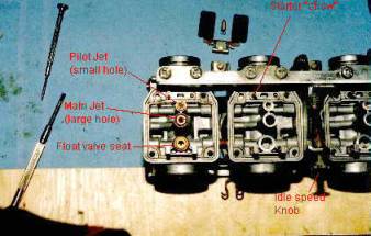
Look at this picture carefully! At least one of the aftermarket manuals out there mixed up the air jets in their pictures!
The main air jet has the SMALL hole, and goes in the center. The pilot air jet has the LARGE hole, and goes to the engine side.
The empty spot is for the cover retaining screw, shown later. Also shown here is the synchronizing screw locations and the pilot mixture screw. Assemble the spring, washer and o-ring to the mixture screw and gently wind the screw in until it just seats. Back it out 2 ½ turns to start.
Install the cover over the air jets using the special retaining screw. It has an extra head to prevent warping the cover when it’s tightened.
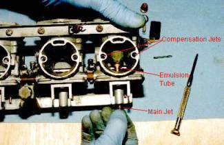
Insert the emulsion tube into the hole through the top of the carburetor. The main jet retains it with its washer. A little finger pressure on the tube will prevent it from turning while the jet is tightened. The main jet has the large hole of the two jets that have heads.
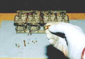
Don’t forget about the compensation jets, located on either side of the carb throat. They are easily identified, having the largest holes of all the jets.
The starter plunger has a rubber dust seal that can be a bit tricky to reinstall, but a small screwdriver helps ease the rubber over the flange.
The underbelly of the rack. Note the pilot jet has the small hole, and no washer.
Orientation of the float and needle. The needle has a rubber tip, and so was not soaked overnight, just rinsed and wiped with a soft clean cloth. Be careful when handling the floats, so as to avoid bending the thin metal frame.
Assemble the needle, spring, and retainer in the piston with an Allen key. Remember the spring goes between the needle and retainer! The needle will not sit dead straight. This is deliberately skewed by a small brass dowel pressed into the piston. The manufacturer claims atomization of the fuel is more efficient if the needle is resting against one side of the emulsion tube.
Insert the piston. It may be necessary to gently guide the needle into the emulsion tube.
Carefully seat the diaphragm all the way around in the groove. There’s an index tab on the diaphragm that fits into the corresponding notch in the casting. If this is not carefully seated, an air leak will result in very poor performance.
Don’t forget to put the big spring in the centre of the piston before reinstalling the domed cover. The flattened side of the cover goes towards the air box end of the carb.
Reassemble the start plunger actuating shaft and arms.
An easy way to set the float heights. The bowls are installed with one screw each so they can be easily removed and adjusted. The bank is gently clamped in the Workmate and leveled, leaving the bowls accessible. This way, the level can be adjusted without having to repeatedly install and remove the carbs from the bike. See Bench Checking Fuel Levels for a complete description of the procedure.