TCI Identification
The following is a guide to determing if a used TCI is appropriate for a given machine:
The following is a guide to determing if a used TCI is appropriate for a given machine:
This series assumes you took the carbs apart, and are trying to figure out how to put them back together again. If you haven’t taken them apart yet, it’s a good idea to skim through this first anyway. Address any questions to: xj-owners@micapeak.com, and we’ll try to talk you through it.
Pictures and text by Dwayne Verhey
2. Lower crankcase
a. Install the shift cam and secure it with the guide pin. Install the stopper plate and bolt and tighten securely.
b. Install the neutral switch.

c. Install the transmission drive axle assembly into the crankcase.
5. Clutch assembly
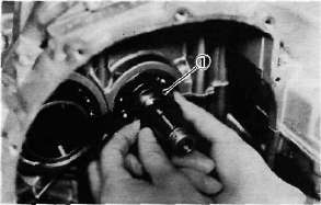
a. Install the thrust plate onto the transmission main axle.

1. Thrust plate
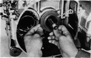
b. Install the oil pump drive sprocket onto the main axle without the spacer collar and place the oil pump drive chain on its sprocket.

1. Oil pump drive sprocket
ELECTRIC STARTING SYSTEM
STARTING CIRCUIT OPERATION
The starting circuit on this model consists of the starter motor, starter relay, and the starting-circuit cut-off relay. If the engine stop switch and the main switch are both on, the starter motor can operate only if:
a. The transmission is in neutral (the neutral switch is on).
or if
C. Middle Gear Servicing
1. Disassembly
Refer to page 39 for disassembly.
2. Inspection
Refer to page 52 for inspection.
3. Gear lash check
NOTE:---------------------------------------------------
11. Pistons and Cylinder a. Install the pistons on the rods. The arrow on the piston must point to the front of the engine.
NOTE:--------------------------------------------------------
Before installing the piston pin clips, cover
the crankcase with a clean rag so you will
not accidentally drop the circlip into the
crankcase.
8. A.C. Generator
a. Install the rotor onto the shaft and
tighten the bolt using the rotor holding
tool (special tool) as shown.

1. Rotor holding tool
Tightening torque: 5.5 m-kg (39.8 ft-lb)
12. Cylinder head and Cam shafts
a. Install the new cylinder head gasket. Install the dowel pins and "O-rings". Locate the cam chain cavity cylinder seal with the tabs down.

b. Install the cylinder head onto the cylinder. Pull the cam chain through the cylinder head as it is installed. Tie the cam chain so that it does not fall into the crankcase.
P. Middle Gear
1. Damper disassembly
NOTE:-------------------------------------------------------
Disassembly of the middle gear damper requires the damper compressor (special tool) and a hydraulic press.
a. Place the middle drive shaft in a press with the damper compressor (special tool) in place as shown.