Chapter 8, APPENDICES
Chapter 8, APPENDICESGeneral Specifications
General SpecificationsGENERAL SPECIFICATIONS
|
Item |
Model |
XJ750XN |
Model Code Number Federal V.I.N. Number Engine Starting Number |
1FL JYA1FL00 * FA000101 1FL-000101 |
Dimensions: Overall Length Overall Width Overall Height Seat Height Wheelbase Minimum Ground Clearance |
2,235 mm (88.0 in) 775 mm (30.5 in) 1,160 mm (45.7 in) 760 mm (29.9 in) 1,520 mm (59.8 in) 145 mm ( 5.7 in) |
Basic Weight: With Oil and Full Fuel Tank |
232 kg (511 lb) |
Minimum Turning Radius: |
2,800 mm (110.2 in) |
Engine: Engine Type Cylinder Arrangement Displacement Bore x Stroke Compression Ratio Compression Pressure Starting System |
Liquid cooled 4-stroke, gasoline, DOHC 4-cylinder parallel 749 cm3 (45.69 cu.in) 68.0 x 51.6 mm J2.677 x 2.032 in) 11.2:1 1,098 kPa (11.2 kg/cm2, 159 psi) at 300 r/min Electric starter |
Lubrication System: |
Pressure lubricated, wet sump |
Oil Type of Grade: Final Gear Oil |
Yamalube 4-cycle oil or SAE 20W40 type SE motor oil (If temperature does not go below 5°C (40°F).) SAE 10W30 type SE motor oil (If temperature does not go above 15°C (60°F).)
SAE 80API "GL-4" Hypoid gear oil |
Oil Capacity: Engine Oil: Periodic Oil Change With Oil Filter Replacement Total Amount Final Gear Case Oil Amount |
2.5 L(2.2 lmpqt,2.6USqt) 2.8 L (2.5 Imp qt, 3.0 US qt) 3.5 L(3.1 Impqt, 3.7USqt) 0.2 L(0.18 Impqt, 0.21 US qt) |
Radiator Capacity: (Includingall routes) |
2.4 L (2.1 Impqt, 2.5 US qt) |
Air Filter: |
Dry type element |
Fuel: Type Tank Capacity Reserve Amount |
Regular gasoline 13 L(2.9 Imp gal, 3.4 US gal) 3 L (0.7 Imp gal, 0.8 US gal) |
Carburetor: Type Manufacturer |
BS33 x 4, Constant velocity MIKUNI |
|
XJ750XN |
Spark Plug: Type/Manufacturer Gap |
D8ES /NGK or X24ES-U /NIPPONDENSO 0.6 - 0.7 mm (0.024 - 0.028 in) |
Clutch Type: |
Wet, multiple-disc |
Transmission: Primary Reduction System Primary Reduction Ratio Secondary Reduction System Secondary Reduction Ratio Transmission Type Operation Gear Ratio 1st 2nd 3rd 4th 5th |
Spur gear 97/58(1.672) Shaft drive 49/36 x 19/18x32/11 (4.179) Constant-mesh, 5-speed Left foot operation
35/16(2.187) 30/20(1.500) 30/26(1.153) 28/30 (0.933) 26/32(0.812) |
Chassis: Frame Type Caster Angle Trail |
Tubular steel, double cradle 31.5° 120 mm (4.72 in) |
Tire: Type Size(F) Size(R) |
Tubeless 100/90-19 57 H 130/90-16 67H |
Tire Pressure (Cold Tire): Up to 90 kg (198 lb) load* 90 kg (1981b) load- 238 kg (525 lb) load* High Speed Riding *Load is the total weight of cargo, rider, passenger, and accessories. |
FRONT |
REAR |
177 kPa (1.8 kg/cm2, 26 psi) |
196 kPa (2,0 kg/cm2, 28 psi) |
196 kPa (2.0 kg/cm2, 28psi) |
275 kPa (2.8 kg/cm2, 40 psi) |
206 kPa (2.1 kg/cm2, 30psi)
|
226 kPa (2.3 kg/cm2, 32psi) |
Brake: Front Brake Type Operation Rear Brake Type Operation |
Dual disc brake Right hand operation Drum brake Right foot operation |
Suspension: Front Suspension Rear Suspension |
Telescopic fork Swingarm |
Shock Absorber: Front Shock Absorber Rear Shock Absorber |
Coil-Air spring, oil damper Coil spring, oil damper |
Wheel Travel: Front Wheel Travel Rear Wheel Travel |
150 mm (5.9 in) 99 mm (3.9 in) |
Electrical: Ignition System Generator System Battery Type or Model Battery Capacity |
T.C.I. A.C. Generator YB14L 12V 14AH |
Headlight Type: | Semi-sealed beam (Quartz bulb) | Bulb Wattage x Quantity: Headlight Tail/Brake Light Flasher Light | 12V,60W/55W 12V,8W/27Wx2 12V, 27Wx4 |
Indicator Light: Wattage x Quantity:
|
Meter Light "NEUTRAL" "HIGH BEAM" "TURN" "OIL LEVEL" "FUEL" |
12V, 3Wx4 12V, 3Wx 1 12V,3Wx1 12V,3Wx2 12V,3Wx1 12V, 3Wx1 |
Maintenance Specifications -- Engine 750X
Maintenance Specifications -- Engine 750X
|
Model |
XJ750XN |
Cylinder Head: Warp Limit |
0.03 mm (0.0012 in) |
|
*Lines indicate straightedge measurement. |
Cylinder: Bore Size Taper Limit Out-of Round Limit |
68.000 ~ 68.005 mm (2.6772 ~~ 2.6774 in) 0.05 mm (0.002 in) 0.05 mm (0.002 in) |
Camshaft: Drive Method Cam Cap Inside Diameter Camshaft Outside Diameter Shaft to Cap Clearance |
Chain drive (Center) 24.5+0.021-0 mm (0.9646+0.008-0 in) 24.5-0.050-63 mm (0.9646-0.0020-0.0025 in) 0.050 - 0.084 mm (0.0020 - 0.0033 in) |
Cam Dimensions: |
|
Intake "A" <Limit> "B" <Limit> "C" |
32.55-32.65 mm (1.2815- 1.2854 in) 32.45 mm (1.2776 in) 24.95 ~ 25.05 mm (0.9823 - 0.9862 in) 24.85 mm (0.9783 in) 7.5 - 7.7 mm (0.2953 ~ 0.3031 in) |
Exhaust "A" <Limit> "B" <Limit> "C" |
32.40 ~ 32.50 mm (1.2756 - 1.2795 in) 32.30 mm (1.2717 in) 24.95 - 25.05 mm (0.9823 - 0.9862 in) 24.85 mm (0.9783 in) 7.35 - 7.55 mm (0.2894 - 0.2972 in) |
|
Model |
XJ750XN |
Camshaft Runout Limit Cam Chain Type/Number of Links Cam Chain Adjustment Method |
0.03 mm (0.0012 in) Bush chain/112 Automatic |
Valve Clearance (Cold) IN. EX. |
0.11 - 0.20 mm (0.004 - 0.008 in) 0.21 - 0.30 mm (0.008 - 0.012 in) |
Valve Dimensions |
|
"A" Head Dia. "B" Face Width "C" Seat Width "D" Margin Thickness |
|
Stem Outside Diameter <Limit> |
5-0.010-25 mm (0.1969-0.0004-0.0010 in) 4.945 mm (0.1947 in) |
Guide Inside Diameter <Limit> |
5.05 mm (0.199 in) |
Stem-to Guide Clearance <Limit> |
0.010-0.037 mm (0.0004 - 0.0015 in) 0.08 mm (0.003 in) |
Stem-Runout Limit |
0.01 mm (0.0004 in) |
Valve Spring: Free Length Installed Length (Valve Closes) |
|
|
Model |
XJ750N |
Tilt Limit
Inner Spring IN. & EX. Outer Spring IN. & EX.
|
2.5° or 1.7 mm (0.067 in) 2.5° or 1.7 mm (0.067 in)
|
Direction of Winding |
|
Piston: |
Piston Size "D"/ |
68.00-0.012-0.075 mm (2.672-0.0024-0.0030 in) 5 mm (0.20 in) (From bottom line of piston skirt) |
Clearance Between Piston & Cylinder <Limit> Oversize: |
0.06 - 0.08 mm (0.0024 - 0.0031 in) 0.1 mm (0.004 in) 68.50 mm (2.697 in) |
Piston Ring: |
|
Sectional Sketch |
Top Ring
2nd Ring
Oil Ring
|
Barrel Taper Expander
|
|
End Gap (Installed): Top Ring 2nd Ring Oil Ring |
0.30 ~ 0.45 mm (0.012 ~ 0.018 in) 0.20 - 0.35 mm (0.008 - 0.014 in) 0.20 - 0.7 mm (0.008 - 0.028 in) |
Side Clearance: Top Ring 2nd Ring |
0.03 - 0.07 mm (0.0012 - 0.0028 in) 0.03 ~~ 0.07 mm (0.0012 - 0.0028 in) |
|
Model |
XJ750XN |
Connecting Rod: Oil Clearance |
0.032 - 0.056 mm (0.0013 - 0.0022 in) |
Crankshaft: |
|
|
Crank Width "A" Runout Limit "B" Big End Side Clearance "C" Journal Clearance |
341.4 ± 0.6 mm (13.441 ± 0.024 in) 0.03 mm (0.0012 in) 0.160 ~ 0.262 mm (0.0063 - 0.0103 in) 0.020 ~ 0.044 mm (0.0008- 0.0017 in) |
Bearing: Color Code (Corresponding Size) |
1. Blue 1.5 +0.006+0.002 mm (0.0591+0.00024+0.00007 in) 2. Black 1.5 +0.002-0.002 mm (0.0591+0.00007-0.00007 in) 3. Brown 1.5 -0.002-0.006 mm (0.0591-0.00007-0.00024 in) 4. Green 1.5 -0.006-0.010 mm (0.0591-0.00024-0.00039 in) 5. Yellow 1.5 -0.010-0.014 mm (0.0591-0.00039-0.00056 in) |
Clutch: Friction Plate Thickness x Quantity Clutch Plate Thickness x Quantity Warp Limit Clutch Spring Free Length x Quantity Clutch Release Method |
3.0 mm (0.12 in) x 8 2.0 mm (0.079 in) x 7 50.5 mm (2.031 in) x6 Outer Pull |
Transmission: Main Axle Deflection Limit Drive Axle Deflection Limit |
0.08 mm (0.0031 in) 0.08 mm (0.0031 in) |
Shifter: Shifter Type Guide Bar Bending Limit |
Guide bar 0.1 mm (0.004 in) |
Carburetor: Type/Manufacturer/Quantity I.D. Mark Main Jet (MJ.) Main Air Jet (M.AJ.) Jet Needle-clip Position (J.N.) Needle Jet (N.J.) Throttle Valve (Th.V) Pilot Jet (P.J.) Pilot Outlet Size (P.O.) Pilot Air Jet (P.A.J.) Pilot Screw (P.S.) Valve Seat Size (V.S.) Starter Jet (G.S.) Bypath Size (B.P.) Fuel Level (F.L) Float Height (F.H.) Engine Idling Speed Vacuum Pressure at Idling Speed Vacuum Synchronous Difference
|
BS33/MIKUNI/4 1FL00 #105 #120 5FZ83 Y-2 #130 #37.5 00.8 #140 2-1/2 ± 1/2 02.3 *35 00.9 3.0 ± 1.0 mm (0.12 ± 0.04 in) 17.5 ± 1.0 mm (0.69 ± 0.04 in) 1,050± 50r/min 24 ± 1.3 kPa (180± 5 mmHg, 7.1 ± 0.2 inHg) Below 0.7 kPa (5 mmHg, 0.2 inHg)
|
|
|
XJ750XN |
Lubrication System: Oil Filter Type Oil Pump Type Tip Clearance Side Clearance Bypass Valve Setting Pressure Relief Valve Operating Pressure |
Paper Trochoid pump 0.03 ~ 0.09 mm (0.0012 - 0.0035 in) 0.03 ~ 0.08 mm (0.0012 ~ 0.0031 in) 98.0 ± 20kPa (1.0+ 0.2 kg/cm2, 14.2 ± 2.8 psi) 490±49kPa(5.0± 0.5 kg/cm2, 71 ± 7.1 psi) |
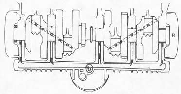
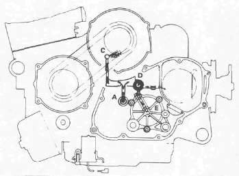
Lubrication Chart |
|
|
Cooling System: Radiator Core Size Radiator Cap Opening Pressure |
300 mm (11.8 in) 78 - 98 kPa (0.8 - 1.0 kg/cm2, 11.4- 14.2 psi) |
Coolant: Total Amount Reservoir Tank Capacity <From Low to FULL Level> |
24.0L (2.11 lmp. qt, 2.54US qt) 0.49 L (0.43 Imp qt, 0.52 US qt) 0.14 L (0.12 Imp. qt, 0.15 US qt) |
Water Pump: Type |
Single Suction Centrifugal Pump |
Thermostat: Opening Temperature Full Open Temperature/Lift |
82°C(180°F) 95°C (203°F)/8mm (0.31 in) |
Shaft Drive: Middle Gear Backlash: Final Gear Backlash: |
0.1 ~ 0.2 mm (0.004 - 0.008 in) 0.1 ~ 0.2 mm (0.004 - 0.008 in) |
|
|
XJ750XN |
Headlight Type: |
Semi-sealed beam (Quartz bulb) |
Bulb Wattage x Quantity: Headlight |
12V, 60W/55W |
Indicator Light: Wattage x Quantity: |
|
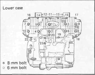
Specifications -- Engine fasteners torque settings
Specifications -- Engine fasteners torque settings
|
Part to be tightened |
Part name |
Thread size |
Q'ty |
Tightening torque |
Remarks |
Nm |
m kg |
ftlb |
Spark plug Cylinder head Cylinder head cover Can cap Can sprocket Can case-Cylinder head Oil check bolt Cover (cylinder head) Drain bolt (cylinder) Cam chain tensioner end plug Cam chain tensioner Cam chain guide Connecting rod Carburetor cover Carburetor joint Air cleaner case cap Air cleaner case Exhaust pipe-Engine Exhaust pipe-Chamber Chamber Chamber-Muffler Muffler stay Muffler |
N/A Nut Bolt Bolt Bolt Bolt Bolt Bolt Bolt Bolt Bolt Bolt Nut Screw Bolt Screw Bolt Nut Bolt Bolt Bolt Bolt Bolt |
M12 P1.25 M9 P1.25 M6 P1.0 M6 P1.0 M7 P1.0 M6 P1.0 M6 P1.0 M6 P1.0 M6 P1.0 M8 P1.25 M6 P1.0 M6 P1.0 M8 P0.75 M5 P0.8 M6 P1.0 M5 P1.0 M6 P1.0 M6 P1.0 M8 P1.25 M8 P1.25 M8 P1.25 M8 P1.25 M8 PI.25 |
4 8 8 40 4 11 1 4 2 1 2 1 8 4 8 3 2 8 4 1 2 2 2 |
17.5 37 10 10 20 10 10 10 10 9 10 10 36 5 12 5 7 10 20 25 25 20 20 |
1.75 3.7 1.0 1.0 2.0 1.0 1.0 1.0 1.0 0.9 1.0 1.0 3.6 0.5 1.2 0.5 0.7 1.0 2.0 2.5 2.5 2.0 2.0 |
12.5 27 7.2 7.2 14 7.2 7.2 7.2 7.2 6.5 7.2 7.2 25 3.6 8.7 3.6 5.1 7.2 14 18 18 14 14 |
Oil
Oil
|
|
Part to be tightened |
Part name |
Thread size |
Q'ty |
Tightening torque |
Remarks |
Nm |
m-kg |
ft-lb |
Oil filter Drain bolt Oil pan Oil pump sprocket Oil pump Oil pump cover Oil delivery pipe Conduit Thermostatic valve Air bleed screw Thermostatic valve cover Radiator Drain bolt (radiator pipe) Drain bolt (radiator) Water pump drive gear cover Water pump drive gear Water pump joint Joint (cylinder) Crankcase Crankcase Main gallery A.C.G. cover Brush A.C. Generator A C.G. bearing housing Starter motor Timing plate Stationaly pointer Pickup coil Clutch cover Clutch cable holder Pressure plate Clutch boss Shift pedal Shift cover Drive axle bearing housing Starter clutch outer Stopper plate (starter idle gear shaft) Drive chain guide (starter) Middle gear: Bearing housing Bearing stopper plate Drive shaft bearing Driven shaft bearing Middle gear flange |
Bolt Bolt Bolt Bolt Bolt Screw Bolt Bolt Bolt Bolt Bolt Bolt Bolt Bolt Screw Bolt Bolt Bolt Bolt Bolt Plug Bolt Screw Bolt TORX screw Bolt Bolt Screw Screw Bolt Bolt Bolt Nut Bolt Bolt Bolt Bolt Bolt Bolt Bolt TORX screw Nut Nut Nut |
M20 P1.5 M14P1.5 M6 P1.0 M6 P1.0 M6 P1.0 M6 P1.0 M10 P1.25 M6 P1.0 M6 P1.0 M6 P1.0 M6 P1.0 M6 P1.0 M6 P1.0 M8 PI.25 M6 P1.0 M6 P1.0 M6 P1.0 M6 P1.0 M8 P1.25 M6 P1.0 M20 P1.5 M6 P1.0 M6 P1.0 M10 P1.25 M6 P1.0 M6 P1.0 M8 PI.25 M6 P1.0 M6 P1.0 M6 P1.0 M6 P1.0 M6 P1.0 M20 P1.0 M6 P1.0 M6 P1.0 M6 P1.0 M8 P1.25 M6 P1.0 M6 P1.0 M8 PI .25 M8 P1.25 M34P1.0 M65P1.5 M14P1.5 |
1 1 13 1 3 4 3 2 1 1 2 3 1 1 2 1 1 4 19 20 2 3 2 1 3 2 1 1 2 10 2 6 1 1 10 3 3 1 2 4 4 1 1 1 |
15 43 12 12 12 7 21 7 10 10 10 7 7 2.9 8 12 10 10 24 12 12 12 8 55 10 7 24 8 8 12 12 8 70 8 12 12 25 8 8 25 25 110 110 90 |
1.5 4.3 1.2 1.2 1.2 0.7 2.1 0.7 1.0 1.0 1.0 0.7 0.7 0.3 0.8 1.2 1.0 1.0 2.4 1.2 1.2 1.2 0.8 5.6 1.0 0.7 2.4 0.8 0.8 1.2 1.2 0.8 7.0 0.8 1.2 1.2 2.5 0.8 0.8 2.5 2.5 11 11 9.0 |
11 31 8.7 8.7 8.7 5.1 15 5.1 7.2 7.2 7.2 5.1 5.1 2.2 5.8 8.7 7.2 7.2 17 8.7 8.7 8.7 5.8 40 7.2 5.1 17 5.8 5.8 8.7 8.7 5.8 50 5.8 8.7 8.7 18 5.8 5.8 18 18 80 80 65 |
-- -- -- -- -- -- -- -- -- -- -- -- -- -- -- oil -- -- oil oil oil -- -- -- oil -- -- -- -- -- -- -- -- -- -- -- Stake / oil -- -- oil -- Stake -- Stake / oil |
Maintenance Specifications -- Chassis
Maintenance Specifications -- ChassisChassis
|
Steering System: Steering Bearing Type |
Taper Roller Bearing |
Front Suspension: (Each) Front Fork Travel Fork Spring Free Length Spring Rate/Stroke Optional Spring Oil Capacity Oil Grade Enclosed Air Pressure: Standard Minimum- Maximum |
150 mm (5.9 in) 511 mm (20.1 in) K, = 3.92 N/mm (0.40 kg/mm, 22.4 lb/in) 0- 100 mm (0- 3.94 in) K2 = 4.90 N/mm (0.50 kg/mm, 28 lb/in) 100- 150 mm (3.94- 5.90 in) No. 389 cm3 (13.7 Imp oz, 13.2 US oz) YAMAHA Fork & Shock Oil 10wt or equivalent fork oil 39.2 kPa (0.4 kg/cm2, 5.7 psi) Zero- 118 kPa (Zero - 1.2 kg/cm2, Zero - 17.1 psi) |
Rear Suspension: (Each) Shock Absorber Travel Spring Free Length Spring Fitting Length Spring Rate/Stroke |
70 mm (2.76 in) 243.5 mm (9.59 in) 217.5 mm (8.56 in) K, = 21.6 N/mm (2.2 kg/mm, 123.2 lb/in) |
Rear Arm: Swingarm Free Play Limit: |
|
Wheel: Front Wheel Type Rear Wheel Type Front Rim Size/Material Rear Rim Size/Material Rim Runout Limit: |
Cast Wheel Cast Wheel MT2.15x 19/Aluminum MT3.00x 16/Aluminum
|
Disc Brake: Outside Dia. x Thickness |
267 x 5 mm (10.5 x 0.2 in) |
Pad Thickness:
|
Inner Outer |
5.5 mm (0.22 in) 5.5 mm (0.22 in) |
Master Cylinder Inside Dia. Caliper Cylinder Inside Dia. Brake Fluid Type |
15.87 mm (0.62 in) 38.18 mm (1.50 in) DOT #3 |
Drum Brake: Type Rear Drum Inside Dia. <Limit> Lining Thickness <l_imit> Shoe Spring Free Length
|
Leading trailing 200 mm (7.87 in) 201 mm (7.91 in) 4 mm (0.16 in) 2 mm (0.08 in) 68 mm (2.7 in)
|
Brake Lever & Brake Pedal:
Brake Lever Free Play Brake Pedal Position Brake Pedal Free Play |
2-5mm (0.08 - 0.20 in)/at lever end 10 mm (0.4 in) below the top of the footrest 20-30mm (0.8- 0.12 in) |
Clutch Lever Free Play: | 2 - 3 mm (0.08 - 0.12 in)/at lever pivot |
Tightening torque
|
Part to be tightened |
Part name |
Thread size |
Q'ty |
Tightening torque |
Remarks |
Nm |
m-kg |
fflb |
Engine mounting bolt: |
|
|
|
42 |
4.2 |
30 |
|
Rear |
Nut |
M12 P1.25 |
2 |
90 |
9.0 |
65 |
|
Engine mounting stay |
Nut |
M8 P1.25 |
4 |
33 |
3.3 |
24 |
|
Downtube |
Bolt |
M8 P1.25 |
4 |
33 |
3.3 |
24 |
|
Downtube & Cross pipe |
Nut |
M8 P1.25 |
2 |
33 |
3.3 |
24 |
|
Handle crown & Steering shaft |
Nut |
M20 P1.0 |
1 |
110 |
11 |
80 |
Ring nut (Lower) |
Nut |
M22 P1.0 |
1 |
6 |
0.6 |
4.3 |
See page 6-25 |
Handle crown & Inner tube |
Nut |
M8 P1.25 |
2 |
20 |
2.0 |
14 |
|
Handle crown & Handlebar holder |
Bolt |
M8 PI.25 |
4 |
20 |
2.0 |
14 |
|
Under bracket & Inner tube |
Bolt |
M8 PI.25 |
4 |
23 |
2.3 |
17 |
Front wheel axle |
Nut castle |
M14 P1.5 |
1 |
105 |
10.5 |
75 |
|
Front wheel axle pinch bolt |
Nut self locking |
M8 P1.25 |
1 |
20 |
2.0 |
14 |
|
Pivot shaft (Right) |
Bolt |
M22P1.5 |
1 |
5.5 |
0.55 |
4.0 |
Taper roller bearing |
Pivot shaft (Left and Right) |
Bolt/Nut |
M22P1.5 |
1 |
100 |
10.0 |
72 |
|
Rear wheel axle |
Nut castle |
M14P1.5 |
1 |
105 |
10.5 |
75 |
|
Rear wheel axle pinch bolt |
Bolt |
M8 P1.25 |
1 |
20 |
2.0 |
14 |
Rear shock absorber (Upper). |
Nut cap |
M8 P1.25 |
2 |
20 |
2.0 |
14 |
Rear shock absorber (Lower) |
L Nut cap R Bolt |
M10P1.25 |
2 |
30 |
3.0 |
22 |
|
Footrest |
Bolt |
M8 P1.25 |
4 |
29 |
2.9 |
21 |
|
Tension bar & Brake plate |
Bolt |
M8 P1.25 |
1 |
20 |
2.0 |
14 |
|
Tension bar & Rear arm |
Bolt |
M8 P1.25 |
1 |
20 |
2.0 |
14 |
|
Camshaft lever & Camshaft |
Bolt |
M6 P1.0 |
1 |
9 |
0.9 |
6.5 |
|
Disc brake section: Brake disc & Hub (Front) |
Bolt |
M8 P1.25 |
12 |
20 |
2.0 |
14 |
|
Master cylinder & Brake hose (Front) |
Bolt union |
M10 P1.25 |
1 |
26 |
2.6 |
19 |
|
Brake hose & Joint |
Bolt union |
M10 P1.25 |
1 |
26 |
2.6 |
19 |
|
Caliper & Brake hose |
Bolt union |
M10 P1.25 |
2 |
26 |
2.6 |
19 |
|
Caliper & Front fork (Front) |
| |
M10 P1.25 |
4 |
35 |
3.5 |
25 |
|
Caliper bleed screw (Ftont) |
I |
M8 P1.25 |
2 |
6 |
0.6 |
4.3 |
|
Front fender |
Bolt |
M6 P1.0 |
4 |
9 |
0.9 |
6.5 |
|
Final gear & Rear arm |
Nut |
M10P1.25 |
4 |
42 |
4.2 |
30 |
Final gear: |
Drive shaft |
Nut |
M14P1.5 |
1 |
110 |
11 |
80 |
Oil |
Bearing housing |
Flange bolt |
M8 PI.25 |
4 |
25 |
25 |
18 |
Bearing housing |
Nut |
M8 P1.25 |
6 |
23 |
2.3 |
17 |
Oil filler cap |
Plug |
M14P1.5 |
1 |
23 |
2.3 |
17 |
Oil drain screw |
Plug |
M14P1.5 |
1 |
23 |
2.3 |
17 |
Bearing retainer |
- |
M65P1.5 |
1 |
110 |
11 |
80 |
Left-hand thread |
Cross joint |
Hexagon bolt with washer |
M8 PI .25 |
4 |
44 |
4.4 |
32 |
Muffler bracket & Frame |
Bolt |
M8 PI.25 |
3 |
23 |
2.3 |
17 |
Rear fender |
Bolt |
M10P1.25 |
2 |
32 |
3.2 |
23 |
Muffler bracket & Muffler |
Bolt |
M10P1.25 |
2 |
25 |
2.5 |
18 |
General Torque Specifications
General Torque SpecificationsGENERAL TORQUE SPECIFICATIONS
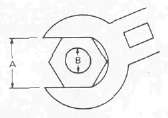
This chart specifies torque for standard fasteners with standard l.S.O. pitch threads. Torque specifications for special components or assemblies are included in the applicable sections of this book. To avoid warpage, tighten multi-fastener assemblies in a criss-cross fashion, in progressive stages, until full torque is reached. Unless otherwise specified, torque specifications call for clean, dry threads. Components should be at room temperature.
|
A (Nut) |
B (Bolt) |
General torque specifications |
Nm |
m-kg |
ft-lb |
10 mm |
6 mm |
6 |
0.6 |
4.3 |
12 mm |
8 mm |
15 |
1.5 |
11 |
14 mm |
10 mm |
30 |
3.0 |
22 |
17 mm |
12 mm |
55 |
5.5 |
40 |
19 mm |
14 mm |
85 |
8.5 |
61 |
22 mm |
16 mm |
130 |
13.0 |
94 |
DEFINITION OF UNITS
|
Unit |
Read |
Definition |
Measure |
mm cm |
millimeter centimeter |
10"3 meter 10-2 meter |
Length Length |
kg |
kilogram |
103 gram |
Weight |
N |
Newton |
1 kg x m/sec2 |
Force |
Nm |
Newton meter |
N x m |
Torque |
Pa N/mm |
Pascal Newton per millimeter |
N/m2 N/mm |
Pressure Spring rate |
L cm3 |
Liter Cubic centimeter |
|
Volume or Capacity |
r/min |
Rotation per minute |
|
Engine Speed |
Maintenance Specifications -- Electrical
Maintenance Specifications -- Electrical
Electrical
|
Voltage: 12V |
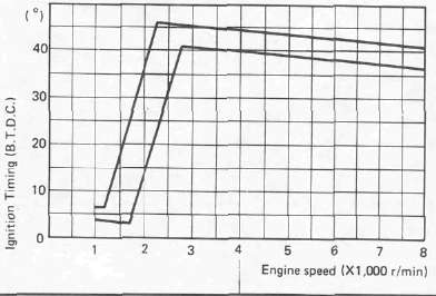
Ignition System: Ignition Timing (B.T.D.C.) 5° at 1,100 r/min |
 |
|
T.C.I.: Pickup Coil Resistance T.C.I. Unit — Model/Manufacturer |
120Ω ± 10% at 20°C (68°F) TID14-35/HITACHI |
Ignition Coil: Model/Manufacturer Minimum Spark Gap Primary Winding Resistance Secondary Winding Resistance |
CM12-25/HITACHI 6 mm (0.24 in) or more at 500 r/min 2.7Ω ± 10% at 20°C (68°F) 12 kΩ ± 20% at 20°C (68°F) |
Charging System: Type |
A.C. Generator |
A.C. Generator: Model/Manufacturer Nominal Output |
LD119-19/HITACHI 14V, 26A at 5,000 r/min |
|
Field Coil Resistance Stator Coil Resistance Brush Overall Length Brush Spring Pressure |
4.0Ω ± 10% at 20°C (68°F) (Direct) 0.46Ω ± 10% at 20°C (68°F) (White - White) 17 mm (0.67 in) 190-360 g (6.7- 12.7 oz) |
Voltage Regulator: Type Model/Manufacturer No Load Regulated Voltage |
Semi conductor. Field control SH233-12/SHINDENGEN 14.5 ± 0.3V |
Rectifier: Model/Manufacturer Capacity |
SH233-12/SHINDENGEN 35A |
Battery: Capacity Specific Gravity |
12V 14AH 1.280 |
|
Electric Starter System: Type Starter Motor: Model/Manufacturer Output Armature Coil Resistance Brush: Spring Pressure Commutator Diameter: Wear Limit Mica Undercut Starter Relay: Amperage Rating |
Constant-mesh type ADB4D2/NIPPONDENSO 0.6 kW 0.014Ω ±6% at 20°C(68°F)
12 mm (0.47 in) 800 ± 150 g (28.22 ± 5.29 oz) 28 mm (1.10 in) 27 mm (1.06 in) 0.4 - 0.8 mm (0.02 ~ 0.03 in)
150A |
Horn: Type x Quantity Model/Manufacturer Maximum Amperage |
Plain type x 2 CF12/NIKKO |
Relay Assembly: Model/Manufacturer Flasher Relay: Type Self Cancelling Device Flasher Frequency Wattage Starting-Circuit Cut-off Relay: Color Code |
FX257N2/NIPPONDENSO Semi Transistor Type Yes 60- 120cycle/min 27W x 2 pcs + 3W No. |
Sidestand Relay: Model/Manufacturer Color Code |
G2MW-D-3636/TATEISHI Blue |
Oil Level Switch: Model/Manufacutrer |
4H7/NIPPONDENSO |
Fuel Level Sender: Winding Coil Resistance |
1.1 ±0.2kΩ at20°C(68°F) |
Circuit Breaker: Type Amperage for Individual Circuit x Quantity: MAIN HEADLIGHT SIGNAL IGNITION FAN RESERVE |
Fuse
30Ax 1 15Ax 1 15Ax 1 10Ax 1 10Ax 1 30Ax 1 |
|
|
XJ750XN |
Headlight Type: |
Semi-sealed beam (Quartz bulb) |
Bulb Wattage x Quantity: Headlight |
12V, 60W/55W |
Indicator Light: Wattage x Quantity: |
|
Lubrication Diagrams
Lubrication DiagramsLUBRICATION DIAGRAM
Cable Routing
Cable RoutingCABLE ROUTING (1)


1 Cover
2 Meter
3 Handlebar switch (Left) lead
4 Clutch switch lead
5 Cable guide
6 Clutch cable
7 Starter cable
8 Front flasher light (Left) lead
9 Main switch lead
10 Front brake hose
11 Throttle cable
12 Front flasher light (Right) lead
13 Cable guide
14 Front brake switch lead
15 Handlebar switch (Right) lead
16 Wire harness
17 Black coupler
18 Red coupler
19 Brown coupler
A Pass the speedometer cable between under bracket and outer cover.
CABLE ROUTING (2)
1 Front brake hose
2 Radiator fan motor lead
3 Clutch cable holder
4 Battery negative (-) lead
5 Rear brake switch
6 Clamp
7 Clamp
8 Clutch cable
9 Starter cable
10 Wireharness
11 Throttle cable
12 Band
13 Clamp
14 Cover
15 Reservoir tank breather pipe
16 Reservoir tank
17 Radiator fan
18 Ignition coil
19 Radiator cap
20 Band
21Crankcase
22 Starter lead
A Pass the wireharness and throttle cable outside the cover 1.
B Pass the clutch cable between the air cleaner joint #3 and #4.
C Pass the hose between the radiator hose and cover 1.
D Pass the hose between the ignition coil and down tube
E Pass the hoses between the down tube and radiator
F Clamp the pick up coil lead and A.C. generator lead
CABLE ROUTING (3)
1 Horn lead (Left)
2 Ground lead
3 Clamp
4 Reservoir tank breather hose
5 Cable holder
6 Speedometer cable
7 Clamp
8 Front brake hose
9 Starter cable
10 Clutch cable
11 Throttle cable
CABLE ROUTING (4)
1 A.C. generator lead
2 Sidestand switch lead
3 lgniter lead
4 Diode assembly
5 Sidestand relay lead
6 Rectifier-regulator assembly
7 Neutral switch lead
8 Oil level switch lead
9 Pickup coil lead
10 Clamp
11 Sidestand switch assembly
12 Starter motor lead
13 Locating damper
14 Fuel sender
15 Battery negative (-) lead
16 Clamp
17 Sidestand switch lead
18 Pickup coil lead
19 Air cleaner drain hose
20 Battery breather hose
21 A.G. generator lead
22 Starter motor lead
23 Rear arm
24 Rear brake switch
A Insert the lead inside the bridge plate
B Push the fuel sender lead into the locating damper
CABLE ROUTING (5)
1 Ignition coil leads
2 Radiator fan motor lead
3 Thermostat lead
4 Horn lead (Right)
5 Earth lead
6 Wireharness
7 Band
8 Rear brake switch lead
9 Battery negative (-) lead
10 Starter switch lead
11 Fuse holder assembly
12 Rear flasher light lead (Right)
13 Clamp
14 Taillightlead
15 Rear flasher light lead (Left)
16 Ignition coil lead (Left)
17 Starter lead (Starter motor - Starter relay)
18 Battery positive (+) lead
19 Starter lead (Battery (+) - Starter relay)
20 To fuel sender
21 Relay assembly
22 Horn lead
23 Thermostat unit
24 Ignition coil (Right)
25 Ignition coil (Left)
26 "1"mark ->#1 cylinder
27 "2" mark -> #2 cylinder
28 "3" mark -> #3 cylinder
29 "4" mark -> #4 cylinder
A Align the white tape on wireharness with the cross tube.
B When installing the seat, be careful not to pinch the leads.


