Chapter 8. Exploded Diagrams
Chapter 8. Exploded DiagramsEngine Components
Engine ComponentsCYLINDER HEAD
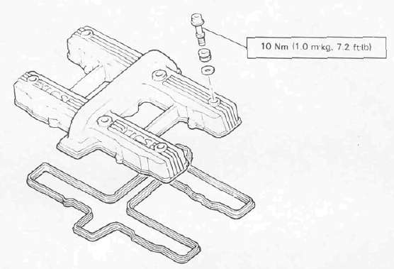

VALVE

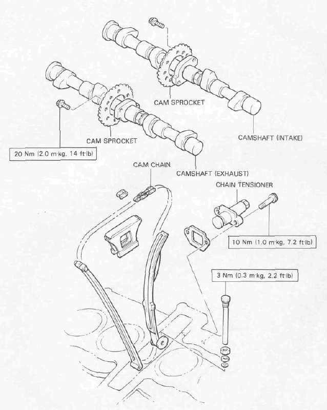
CAM CHAIN
CRANKSHAFT/PISTON

. WHEN INSTALLING THE CONNECTING ROD. BE SURE THAT THE SECURING NUTS ARE ON TOP.

OIL COOLER

Transmission Components
Transmission ComponentsCLUTCH

TRANSMISSION

MIDDLE GEAR/DAMPER
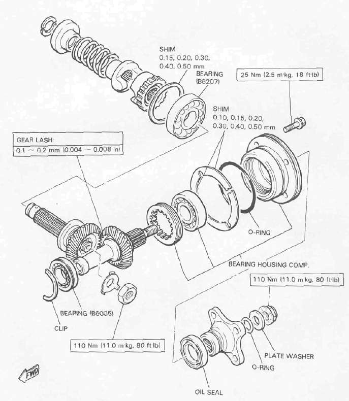
Final Drive
Final DriveFINAL GEAR/DRIVE SHAFT
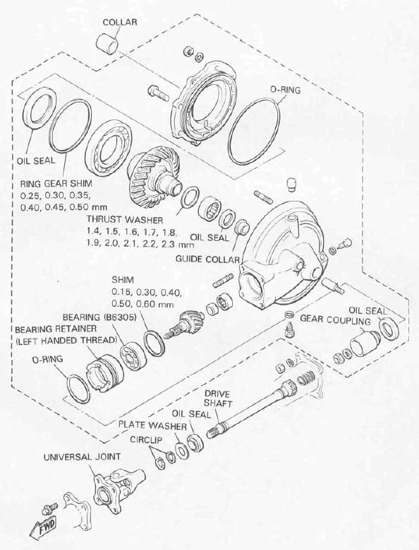
Wheels and Brakes
Wheels and BrakesFRONT MASTER CYLINDER
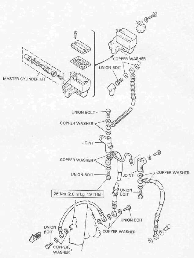
REAR MASTER CYLINDER

FRONT BRAKE CALIPER
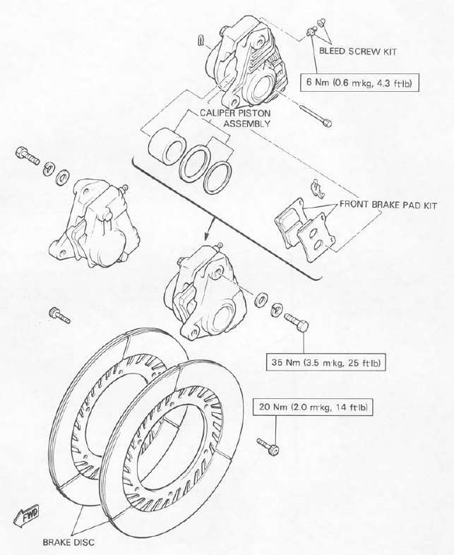
REAR BRAKE CALIPER

FRONT WHEEL

REAR WHEEL

Suspension Components
Suspension ComponentsFRONT FORK
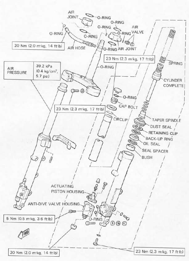
REAR SHOCK ABSORBER

SWING ARM

• APPLY LITHIUM-BASE GREASE
Lubrication Diagrams
Lubrication DiagramsLUBRICATION DIAGRAMS


Cable Routing
Cable RoutingCABLE ROUTING
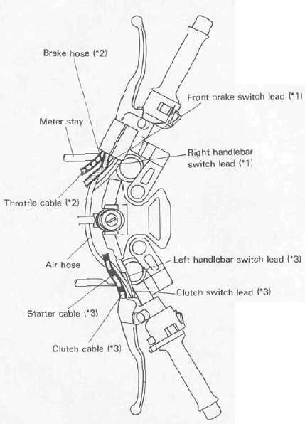
*1: Pass front brake switch lead and right handlebar switch lead behind air hose.
*2: Pass brake hose and throttle cable between air hose and meter stay.
*3: Pass clutch cable, clutch switch lead, left handlebar switch lead and starter cable behind air hose.
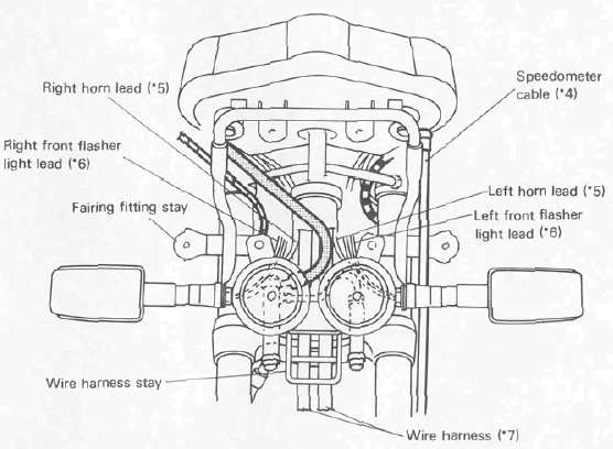
*4: Pass speedometer cable outside meter stay, in front of fairing fitting stay, and outside brake hose.
*5: Pass horn leads in front of brake joint.
*6: Pass front flasher light leads between horn and brake joint.
*7: Pass wire harness between under bracket and wire harness stay.
*1: Fasten ground lead together left ignition coil.
*2: Pass clutch cable between air cleaner joint #3 and #4
Electrical
ElectricalSPEEDOMETER/TACHOMETER
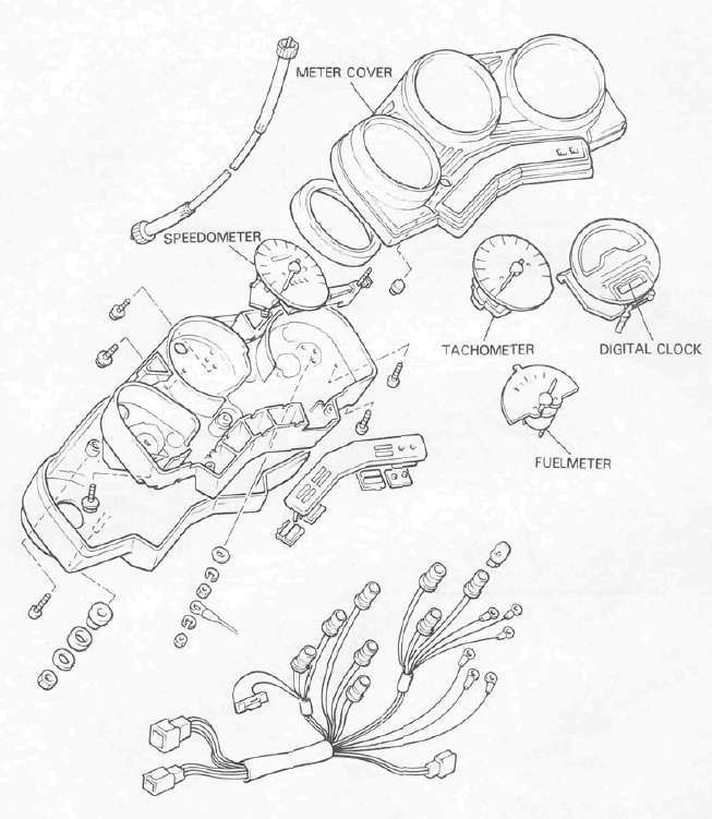
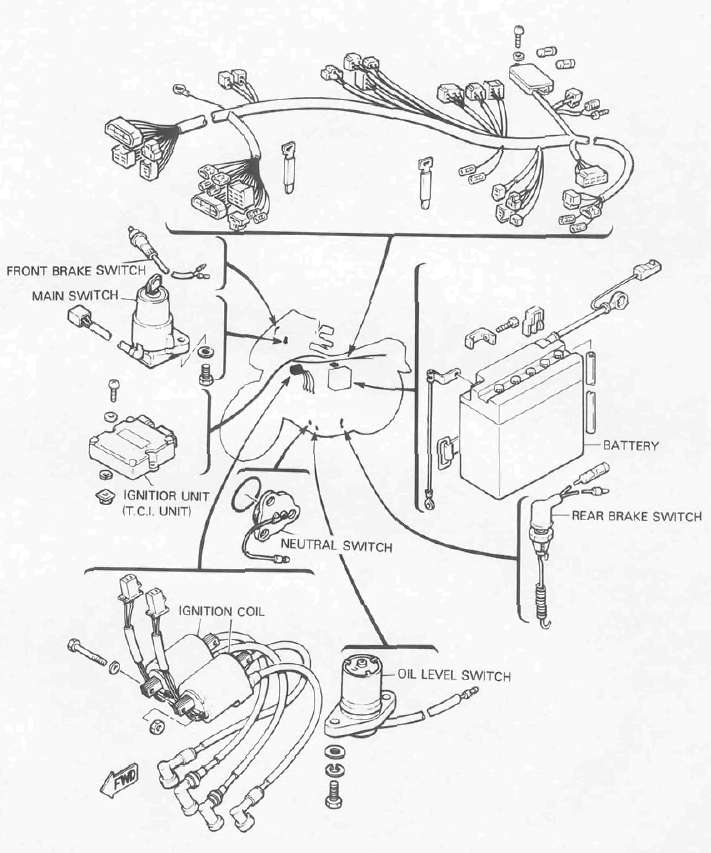
ELECTRICAL 1
ELECTRICAL 2
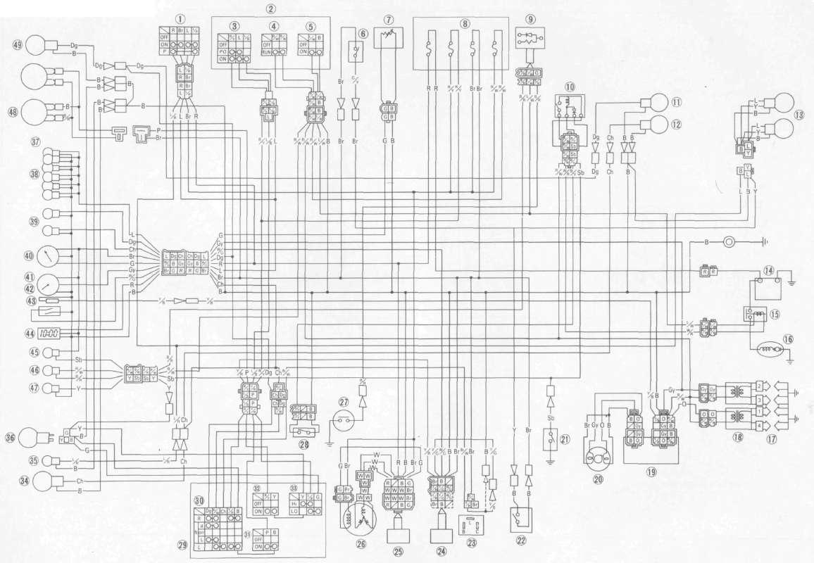
WIRING DIAGRAM
| 1 | Main switch | 25 | Rechfier with regulator |
| 2 | Handlebar switch (Right) | 26 | AC. Generator |
| 3 | "LIGHTS" switch | 27 | Oil level switch |
| 4 | "ENGINE STOP" switch | 28 | Clutch switch |
| 5 | "START" switch | 29 | Handlebar switch (Left) |
| 6 | Front brake switch | 30 | "TURN" switch |
| 7 | Fuel sender | 31 | "HORN" switch |
| 8 | Fuse box | 32 | Passing light switch "PASS" |
| 9 | Diode | 33 | "LIGHTS" (Dimmer) switch |
| 10 | Starting-circuit cut-off relay | 34 | Front flasher light (Left) |
| 11 | Rear flasher light (Right) | 35 | Auxiliary light |
| 12 | Rear flasher light (Left) | 36 | Headlight |
| 13 | Tail/brake light | 37 | Meter assembly |
| 14 | Battery | 38 | Meter light |
| 15 | Starter relay | 39 | "TURN" indicator light |
| 16 | Starter motor | 40 | Fuelmeter |
| 17 | Spark plug | 41 | Tachometer |
| 18 | Ignition coil | 42 | Over revolution switch |
| 19 | Ignitor | 43 | Reed switch |
| 20 | Pick-up coil | 44 | Digital clock |
| 21 | Neutral switch | 45 | "NEUTRAL" indicator light |
| 22 | Rear brake switch | 46 | "OIL" indicator light |
| 23 | Flasher relay | 47 | "HIGH BEAM" indicator light |
| 24 | Cancelling unit |
COLOUR CODE
8r | Brown | Y | Yellow | L | Blue | R/W | Red/White | Y/B | Yellow/Black | Y/R | Yellow/Red | E | Ground |
R | Red | Dg | Dark Green | P | Pink | L/W | Blue/White | Br/W | Brown/White | R/W | Red/White | B/R | Black/Red |
W | White | Ch | Chocolate | 0 | Orange | L/B | Blue/Red | Y/G | Yellow/Green | L/R | Blue/Red | Gy | Gray |
B | Black | Sb | Sky Blue | G | Green | R/Y | Red/Yellow | W/G | White/Green | G/Y | Green/Yellow | B/Y | Black/Yellow |
WIRING DIAGRAM


