C. Middle Gear Servicing
1. Disassembly
Refer to page 39 for disassembly.
2. Inspection
Refer to page 52 for inspection.
3. Gear lash check
NOTE:---------------------------------------------------
The middle gear lash can be checked only when the gears are installed in the crankcase.
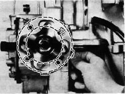
a. Install the middle drive pinion holder (special tool) on the crankcase to hold the drive gear stationary during the lash measurement.
NOTE:----------------------------------------------------
Before installing the tool, loosen the holder bolt all the way out and after installation tighten this bolt as tight as necessary (finder tight is generally sufficient).
1. Middle drive pinion holder
b. Set the dial gauge to the middle drive flange as shown and gently rotate the drive flange back and forth. Note the lash measurement on the dial gauge.
Middle gear lash: 0.1 ~ 0.2mm(0.004~ 0.008 in)
c. Check this engagement at 4 positions. Rotate the drive flange 90° each time and repeat the gear lash check.
NOTE:--------------------------------------------------------
If the gear lash exceeds the specified limit and adjustment is necessary, the engine or swing arm should be removed from the motorcycle.
4. Gear lash adjustment
a. Install the driven gear housing assembly into the crankcase leaving about a 2 mm (0.080 in) gap between the housing and crankcase and install the two bolts to the bearing housing 180° opposite to each other.
a. 2 mm (0.080 in)
b. Install the middle drive shaft holder and dial gauge (refer to "Middle gear lash check").
c. Slowly tighten the bolts alternately until the dial gauge lash measurement reaches 0.2 mm (0.008 in).
d. Measure the gap between the driven gear bearing housing flange and the crankcase with a feeler gauge. This is the shim size required.
1. Feeler gauge
e. Install the proper sized shims as shown and tighten the driven gear housing to the specified torque.
Recheck the gear lash, it should be within the specification, if not readjust the shims.
Gear lash: 0.1 - 0.2 mm (0.004-0.008 in
5. Drive gear positioning
NOTE:------------------------------------------------------
When the following part(s) is replaced with new one(s), drive gear positioning is necessary
a. Crankcase
b. Middle gears
c. Middle gear bearing housing
a. The shim thickness necessary for the drive gear positioning can be calculated from the information found on the upper crankcase and on the drive gear shaft.
b. To find shim thickness "A" use the
formula:
A = c —a — b
Where:
a= a numeral (usually a decimal number) printed on the shaft end as shown above and either added to or subtracted from the nominal size "43".
b = a bearing thickness (considered constant)
c = a numeral (usually a decimal number) found on the upper crankcase half near the main bearing selection numbers and added to the nominal size "60".
Distance "b"^ 16.94 mm
Example:
1)lf the shaft is marked +03 ...... "a" is
43.03 mm.
2) "b" is 16.94 mm.
3) If the crankcase is stamped "45" ..... "c"
is 60.45 mm.
A = c — a —b
A = 60.45 ^16.94-43.03
A = 0.48
Then the necessary shim thickness is
0.48 mm.
c. Shim size are supplied in the following thicknesses:
0.15 mm, 0.20 mm, 0.30 mm, 0.40 mm, and 0.50 mm.
Because the shims can only be selected in 0.05 mm increments the following chart should be used when encountering last digits that are not 5 or zero (0):


|
Last digits |
Rounding |
|
0J.2 |
0 |
|
3,4,5,6,7 |
5 |
|
8,9 |
10 |
- Printer-friendly version
- Log in to post comments