FRONT WHEEL

Removal
1. Place the motorcycle on the center stand.
2. Remove the speedometer cable from the speedometer.
3. Remove the front fender securing bolts and remove the fender.

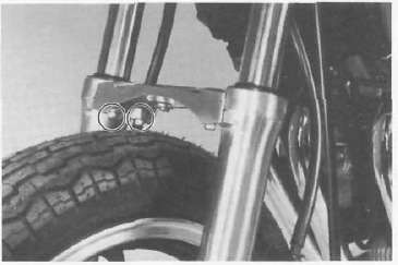
4. Remove the front fork brace securing bolts and remove the brace.
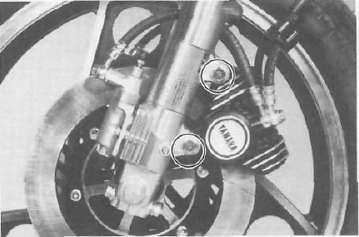
5. Remove the left brake caliper securing bolts and remove the left brake caliper assembly.
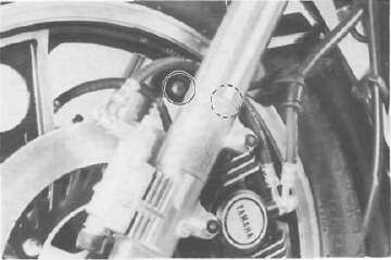
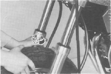
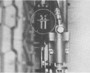
6. Loosen the pinch bolt securing the wheel axle and remove the axle nut.
I. Pinch bolt
7. Remove the axle shaft. In this case, make sure the motorcycle is properly supported.
NOTE: Do not depress the brake lever when the wheel is off the motorcycle as the brake pads will be forced to shut.
8. Lower the wheel until the brake disc comes off the caliper. Turn the right caliper outward so they do not obstruct the wheel and remove the wheel.
Remove any corrosion from the axle with fine emery cloth. Place the axle on a surface plate and check for bends. If bent, replace axle. Do not attempt to straighten a bent axle.
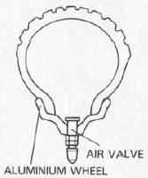
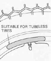
Tubeless tires and aluminum wheels
This motorcycle is equipped with aluminum wheels designed to be compatible with either tube or tubeless tires.
Tubeless tires are installed as standard equipments.
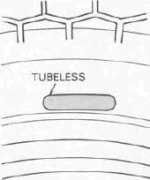
WARNING: Do not attempt to use tubeless tires on a wheel designed for use only with tube-type tires. Tire failure and personal injuly may result from sudden deflation.
Tube-type Wheel — Tube-type Tires only Tubeless type Wheel —
Tube-type or Tubeless tires
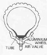
WARNING; When using tube-type tires, be sure to install the proper tube also.
TUBELESS TIRE
TUBE-TYPE TIRE
TIRE
WHEEL
NOTE: Refer to "Tubeless tire and aluminum wheel manual" for the proper tubeless and aluminum wheel servicing.
1. Check for cracks, bends or warpage of wheels. If a wheel is deformed or cracked, it must be replaced.
2. Check wheel run-out. If the deflection exceeds the tolerance below, check the wheel bearings or replace the wheel as required.
Rim-run-out limits:
Vertical - 2 mm (0.08 in) Lateral - 2 mm (0.08 in)
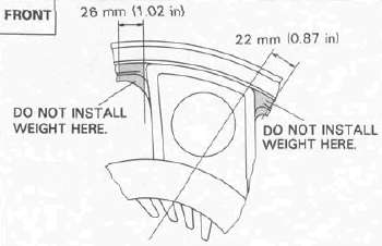
3. Check wheel balance. Rotate the wheel lightly several times and observe resting position. If the wheel is not statically balanced, it will come to reset at the same position each time. Install an appropriate balance weight at lightest position (at top).
NOTE: The wheel should be balanced with the brake disc installed.
CAUTION: Tire and wheel should be balanced whenever either one is changed or replaced. Failure to have wheel balanced can result in poor performance, adverse handling characteristics, and shortened tire life.
4. After installing a tire, ride conservatively to allow the tire to seat itself on the rim properly- Failure to allow proper seating may cause tire failure, resulting in damage to the motorcycle and injury to the rider.
5. After repairing or replacing a tire, check to be sure the valve stem lock nut is securely fastened. It not, torque it as specified.
Tightening torque:
1.5 Nm (0.15 m-kg 1.1 ft lb)
Replacing wheel bearings
If the bearings allow play in the wheel hub or if wheel does not turn smoothly, replace the bearings as follows:
1. Clean the outside of the wheel hub.
2. Drive the bearing out by pushing the spacer aside and tapping around the perimeter of the bearing inner race with a soft metal drift pin and hammer. The spacer "floats" between the bearings. Both bearings can be removed in this manner.
WARNING: Eye protection is recommended when using striking tools.
3. To install the wheel bearing, reverse the above sequence. Use a socket that matches the outside race of the bearing as a tool to drive in the bearing.
CAUTION: Do not strike the center race or balls of the bearing. Contact should be made only with the outer race.
Installing front wheel
When installing the front wheel, reverse the removal procedure. Note the following points:
1. Lightly grease the lips of the front wheel oil seals and the gear teeth of speedometer drive and driven gears. Use lightweight lithium soap base grease.
2. Make sure there is enough gap between the disc pads to slide the disc into place.
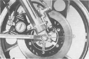
3. Make sure the projecting portion (torque stopper) of the speedometer housing is positioned correctly.
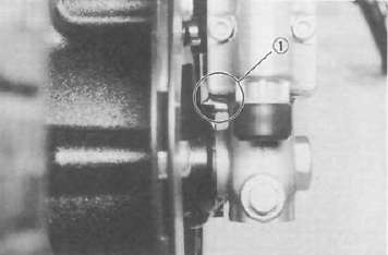
1. Torque stopper
4. Tighten the axle nut.
Axle nut torque:
78 Nm (7.8 m-kg, 50 ft lb)
NOTE: Tighten the pinch bolts temporarily before tightening the axle nut.
5. Install the left brake caliper assembly.
lighting torque 35 Nm (3.5 rrvkg, 25 ft lb)
6. Install the front fork brace.
7. Install the front fender.
8. Before tightening the pinch bolts, stroke the front forks several times to make sure of proper fork operation. With the pinch bolts loose, work the left fork leg back and forth until the proper clearance between the disc and caliper bracket are obtained.
9. Tighten the left and right pinch bolts.
Axle pinch bolt torque: 20 Nm (2.0 m-kg, 14fMb)
- Printer-friendly version
- Log in to post comments