Front fork oil change
WARNING.
1. Fork oil leakage can cause loss of stability and safe handling. Have any problem corrected before operating the motorcycle.
2. Securely support the motorcycle so there is no danger of it falling over.
1. Elevate the front wheel by placing a suitable stand under the engine.
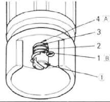
2. Remove the rubber cap from the top of each fork.
3. Remove the air valve cap from the left fork.
4. Keep the valve open by pressing it for several seconds so that the air can be let out of the inner tube.
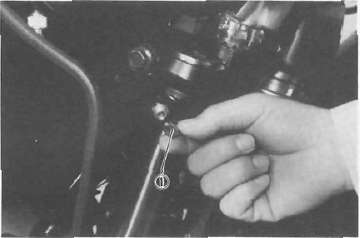
1. Air valve cap
5. Loosen the front fork pinch bolts and remove the cap bolts from the inner fork tubes.

1. Pinch bolt 2. Cap bolt
6. Place an open container under each drain hole. Remove the drain screw from each outer tube.
WARNING:
Do not let oil contact the disc brake components. If any oil should contact the brake components, it must be removed before the motorcycle is operated. Oil will cause diminished braking capacity and will damage the rubber components of the brake assembly.
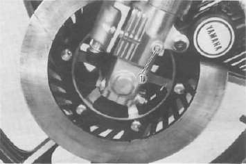
1. Drain screw
7. After most of the oil has drained, slowly pump the forks up and down to remove any remaining oil.
8. Inspect the drain screw gasket. Replace if damaged. Reinstall the drain screws.
9. Pour the specified amout of oil into each the fork inner tube.
Front fork oil capacity (each fork): 286 cm3 (10.1 Imp oz, 9.67 US oz)
Recommended oil: SAE 5W type SE motor oil or equivalent
10. After filling, slowly pump the forks up and down to distribute the oil.
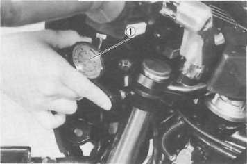
11. Inspect the O-ring on the cap bolt. Replace if damaged.

1. O-ring
12. Reinstall the cap bolt and tighten the pinch bolt.
Tightening torque: Cap bolt: 23 Nm (2.3 mkg, 17 ft-lb) Pinch bolt: 23 Nm (2.3 mkg, 17 ft lb)
13. Fill the fork with air using an air pump or pressurized air supply. Refer to "Front fork and rear shock absorber adjustment" for proper air pressure adjusting.
Maximum air pressure: 118 kPa (1.2 kg/cm2, 17.1 psi) Do not exceed this amount.
Since the right and left front forks are connected by one air hose, there is only one valve where the air pressure is measured and adjusted.
Front fork and rear shock absorber adjustment
Front fork:
1. Elevate the front wheel by placing the motorcycle on the centerstand.
NOTE: When checking and adjusting the air pressure, there should be no weight on the front end of the motorcycle.
2. Remove the valve cap from left fork.
3. Using the air check gauge, check and adjust the air pressure.
If the air pressure is increased, the suspension becomes stiffer and if decreased, it becomes softer.
1. Air gauge
To increase: Use an air pump or pressurized air supply To decrease: Release the air by pushing the valve.
NOTE:
An optional air check gauge is available. Please ask a nearby Yamaha dealer. P/No. 2X4-2811A-00.
Air pressure:
39.2 kPa (0.4 kg/cm2, 5.7 psi) Maximum air pressure:
118 kPa (1.2 kg/cm2, 17.1 psi) Minimum air pressure: Zero
CAUTION: Never exceed the maximum pressure, or oil seal damage may occur.
4. Install the valve cap securely.
Rear shock absorber:
The rear shock absorber of this model features a spring seat, which is a combined spring preload and damping adjuster. Normal adjustment can be made by turning this spring seat; whereas damping adjustment only can be made by the damping adjuster.
CAUTION: Before adjustment, make sure of the following:
1. Turn in the damping adjuster fully. Then turn it back until its red painted slit aligns with the pointer "▼" on the spring cover.
2. For alignment in the absence of the red paint, turn the damping adjuster 6 clicks back from the fully turned-in position.
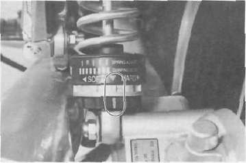
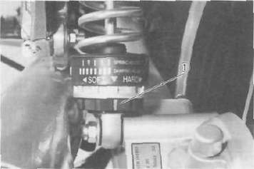
1. Spring seat adjustment
To increase the preload, turn the spring seat clockwise. To decrease the preload, turn the spring seat counterclockwise.
NOTE: When adjusting, use the special wrench which is included in the owner's tool kit
| Hard -------------------------------Soft | |
|
Mark |
|

1. Spring seat
2. Damping adjustment
To increase the damping, turn the adjuster clockwise. To decrease the damping, turn the adjuster counterclockwise.
Standard position:
6 clicks turns out (or red mark) Minimum 12 clicks turns out Maximum 1 clicks turn out
NOTE: Make adjustment in less than one full turn of the adjuster.
1. Damping adjuster
Recommended combinations of the front fork and the rear shock absorber settings.
Use this table as guidance to meet specific riding and motorcycle load conditions.
|
Front frok |
Rear shock absorber |
Loading condition |
|||||
|
Air pressure |
Spring seat |
Damping adjuster turns out |
Solo rider |
With passenger |
With accessory equipment |
With accessory equipments and passenger |
|
|
1 |
39.2 ~ 78.5 kPa (0.4 ~ 0.8 kg/cm2, 5.7 - 11.4 psi) |
|
6 |
O |
|||
|
2 |
39.2 ~ 78.5 kPa (0.4 ~~ 0.8 kg/cm2, 5.7 ~11.4 psi) |
|
4 |
0 |
|||
|
3 |
58.8 - 98.1 kPa (0.6 ~ 1.0 kg/cm2. 8.5 — 14.2 psi) |
|
4 |
O |
|||
|
4 |
78.5 — 118 kPa (0.8 ~ 1.2 kg/cm2, 11.4- 17.1 psi) |
|
3 |
O |
|||


* Each numeral shows the damping value which can be set when the pointer is aligned with the individual slit in the spring seat. The damping adjuster may be further turned for a softer or a harder damping; in each of the above settings, it is recommended that the damping be adjusted by one (1) or two (2) clicks on the softer side and one (1) click on the harder side.
NOTE: Yamaha made a serious error in the original owner's manual regarding the anti-dive adjustment on the 900RK (essentially had it backwards). This is the corrected information, as per the September 1, 1983 TSB:
|
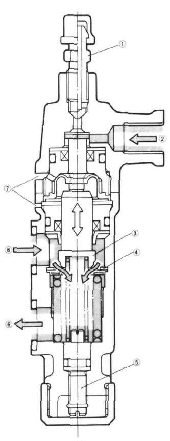
1 |
Air bleed screw |
|
2 |
Brake fluid |
|
3 |
Vaive |
|
4 |
Valve seat |
|
5 |
Adjusting bolt |
|
6 |
Fork oil |
|
7 |
Pilot hole |
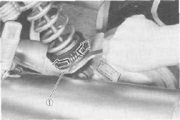
1. Remove the rubber cap from the bottom of the anti-dive unit.

1. Rubber cap
2. Look at the head of the adjusting bolt through the slots in the bottom of the anti-dive unit. In the standard position, two lines will be visible on the adjusting bolt head. Consult the fork adjustment chart below to determine the proper setting.
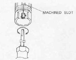
3. To decrease the anti-dive effect turn the adjusting bolt clockwise until the first line appears level to the top of the machined slot(s).
CAUTION: When the first line appears in the machined slot(s), the adjusting bolt will bottom in the anti-dive unit and a resistance will be felt. Do not attempt to turn the adjusting bolt beyond this point or the anti-dive unit will be damaged.
4. To increase the anti-dive effect, turn the adjusting bolt counterclockwise.
5. Replace the rubber cap.
WARNING: The anti-dive settings must be the same on both anti-dive units. Hence, be sure to perform the above procedure on both anti-dive units.
|
Adjusting bolt position |
Loading condition |
||
|
Solo rider |
With accessory equipments or passenger |
Wigh accessory equipments and passenger |
|
|
1 |
O |
||
|
2 |
O |
O |
|
|
3 |
O |
O |
|
|
4 |
O |
||
- Printer-friendly version
- Log in to post comments