Chapter 5. Chassis
Chapter 5. ChassisFront Wheel
Front WheelFRONT WHEEL

Removal
1. Place the motorcycle on the center stand.
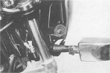
2. Remove the speedometer cable from the speedometer.
3. Remove the front fender securing bolts and remove the fender.

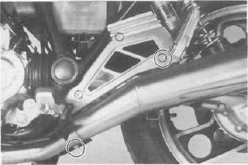
4. Remove the front fork brace securing bolts and remove the brace.
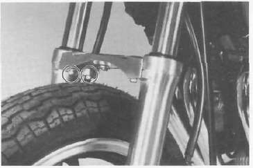
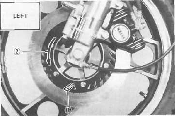
5. Remove the left brake caliper securing bolts and remove the left brake caliper assembly.
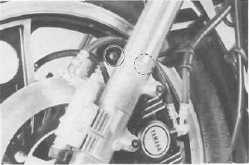
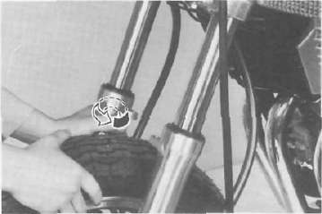
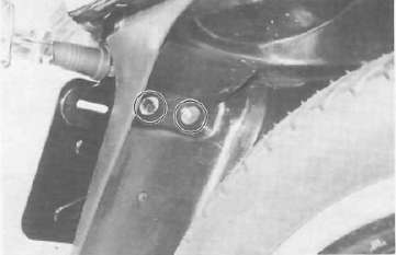
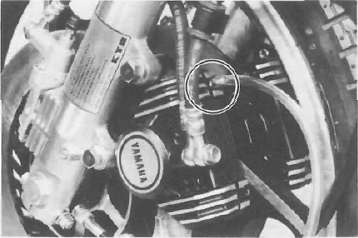
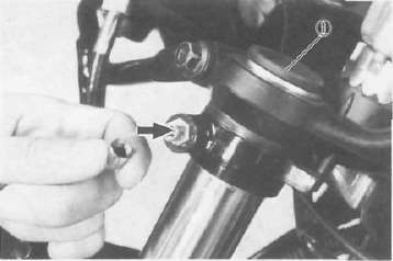
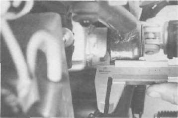
6. Loosen the pinch bolt securing the wheel axle and remove the axle nut.
I. Pinch bolt
7. Remove the axle shaft. In this case, make sure the motorcycle is properly supported.
NOTE: Do not depress the brake lever when the wheel is off the motorcycle as the brake pads will be forced to shut.
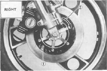
8. Lower the wheel until the brake disc comes off the caliper. Turn the right caliper outward so they do not obstruct the wheel and remove the wheel.
Remove any corrosion from the axle with fine emery cloth. Place the axle on a surface plate and check for bends. If bent, replace axle. Do not attempt to straighten a bent axle.
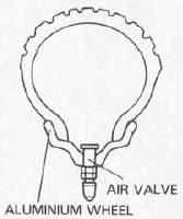
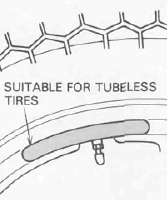
Tubeless tires and aluminum wheels
This motorcycle is equipped with aluminum wheels designed to be compatible with either tube or tubeless tires.
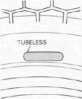
Tubeless tires are installed as standard equipments.
WARNING: Do not attempt to use tubeless tires on a wheel designed for use only with tube-type tires. Tire failure and personal injuly may result from sudden deflation.
Tube-type Wheel — Tube-type Tires only Tubeless type Wheel —
Tube-type or Tubeless tires
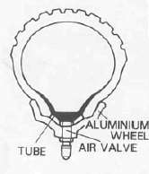
WARNING; When using tube-type tires, be sure to install the proper tube also.
TUBELESS TIRE
TUBE-TYPE TIRE
TIRE
WHEEL
NOTE: Refer to "Tubeless tire and aluminum wheel manual" for the proper tubeless and aluminum wheel servicing.
1. Check for cracks, bends or warpage of wheels. If a wheel is deformed or cracked, it must be replaced.
2. Check wheel run-out. If the deflection exceeds the tolerance below, check the wheel bearings or replace the wheel as required.
Rim-run-out limits:
Vertical - 2 mm (0.08 in) Lateral - 2 mm (0.08 in)
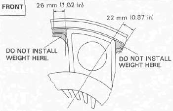
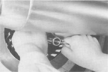
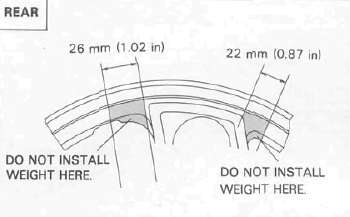
3. Check wheel balance. Rotate the wheel lightly several times and observe resting position. If the wheel is not statically balanced, it will come to reset at the same position each time. Install an appropriate balance weight at lightest position (at top).
NOTE: The wheel should be balanced with the brake disc installed.
CAUTION: Tire and wheel should be balanced whenever either one is changed or replaced. Failure to have wheel balanced can result in poor performance, adverse handling characteristics, and shortened tire life.
4. After installing a tire, ride conservatively to allow the tire to seat itself on the rim properly- Failure to allow proper seating may cause tire failure, resulting in damage to the motorcycle and injury to the rider.
5. After repairing or replacing a tire, check to be sure the valve stem lock nut is securely fastened. It not, torque it as specified.
Tightening torque:
1.5 Nm (0.15 m-kg 1.1 ft lb)
Replacing wheel bearings
If the bearings allow play in the wheel hub or if wheel does not turn smoothly, replace the bearings as follows:
1. Clean the outside of the wheel hub.
2. Drive the bearing out by pushing the spacer aside and tapping around the perimeter of the bearing inner race with a soft metal drift pin and hammer. The spacer "floats" between the bearings. Both bearings can be removed in this manner.
WARNING: Eye protection is recommended when using striking tools.
3. To install the wheel bearing, reverse the above sequence. Use a socket that matches the outside race of the bearing as a tool to drive in the bearing.
CAUTION: Do not strike the center race or balls of the bearing. Contact should be made only with the outer race.
Installing front wheel
When installing the front wheel, reverse the removal procedure. Note the following points:
1. Lightly grease the lips of the front wheel oil seals and the gear teeth of speedometer drive and driven gears. Use lightweight lithium soap base grease.
2. Make sure there is enough gap between the disc pads to slide the disc into place.
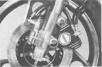
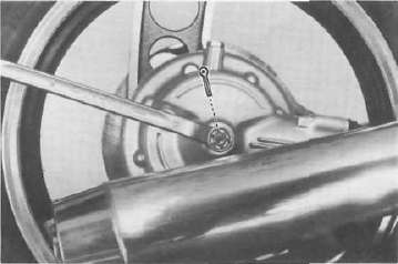
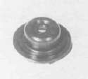
3. Make sure the projecting portion (torque stopper) of the speedometer housing is positioned correctly.
1. Torque stopper
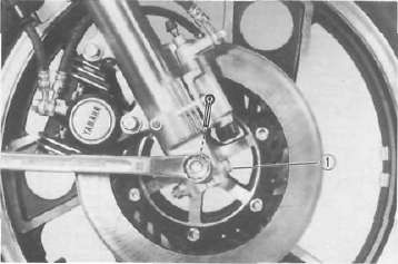
4. Tighten the axle nut.
Axle nut torque:
78 Nm (7.8 m-kg, 50 ft lb)
NOTE: Tighten the pinch bolts temporarily before tightening the axle nut.
5. Install the left brake caliper assembly.
lighting torque 35 Nm (3.5 rrvkg, 25 ft lb)
6. Install the front fork brace.
7. Install the front fender.
8. Before tightening the pinch bolts, stroke the front forks several times to make sure of proper fork operation. With the pinch bolts loose, work the left fork leg back and forth until the proper clearance between the disc and caliper bracket are obtained.
9. Tighten the left and right pinch bolts.
Axle pinch bolt torque: 20 Nm (2.0 m-kg, 14fMb)
Rear Wheel
Rear Wheel 
Removal
1. Place the motorcycle on the center stand.
2. Remove the seat. Next, remove the rear fender installation bolts and remove the rear fender.

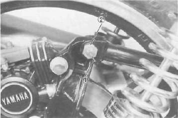
3. Remove the axle nut cotter pin and axle nut.
4. Loosen the rear axle pinch bolt.
1 Pinch belt
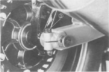
5. Remove the tension bar from the brake caliper assembly. The tension bar can be removed by removing the cotter pin and nut from the tension bar bolt.
1. Cotter pin 2. Tension bar nut
6. While supporting the brake caliper, pull out the rear axle.
7. Hold up the brake caliper assembly.
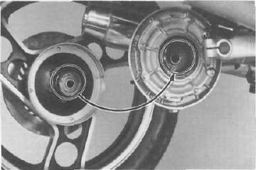
8. Move the wheel to the right side to separate it from the final gear cases and remove the rear wheel.
Rear axle inspection
Remove any corrosion from the axle with fine emery cloth. Place the axle on a surface plate and check for bends. If bent, replace axle. Do not attempt to straighten a bent axle.
Rear wheel inspection
NOTE: Refer to "Tubeless tire and aluminum wheel manual" for the proper tubeless and aluminum wheel servicing.
1. Check for cracks, bends or warpage of wheels. If a wheel is deformed or cracked, it must be replaced.
2. Check wheel run-out. If the deflection exceeds the tolerance below, check the wheel bearings or replace the wheel as required.
Rim-run-out limits:
Vertical - 2 mm (0.08 in) Lateral - 2 mm (0.08 in)
3. Check wheel balance. Rotate the wheel lightly several times and observe resting position. If the wheel is not statically balanced, it will come to reset at the same position each time. Install an appropriate balance weight at lightest position (at top).
NOTE: The wheel should be balanced with the brake disc installed.
CAUTION: Tire and wheel should be balanced whenever either one is changed or replaced. Failure to have wheel balanced can result in poor performance, adverse handling characteristics, and shortened tire life.
4. After installing a tire, ride conservatively to allow the tire to seat itself on the rim properly- Failure to allow proper seating may cause tire failure, resulting in damage to the motorcycle and injury to the rider.
5. After repairing or replacing a tire, check to be sure the valve stem lock nut is securely fastened. It not, torque it as specified.
Tightening torque:
1.5 Nm (0.15 m-kg 1.1 ft lb)
Replacing wheel bearings
If the bearings allow play in the wheel hub or if wheel does not turn smoothly, replace the bearings as follows:
1. Clean the outside of the wheel hub.
2. Drive the bearing out by pushing the spacer aside and tapping around the perimeter of the bearing inner race with a soft metal drift pin and hammer. The spacer "floats" between the bearings. Both bearings can be removed in this manner.
WARNING: Eye protection is recommended when using striking tools.
3. To install the wheel bearing, reverse the above sequence. Use a socket that matches the outside race of the bearing as a tool to drive in the bearing.
CAUTION: Do not strike the center race or balls of the bearing. Contact should be made only with the outer race.
Installing rear wheel
1. Lightly grease lips of rear wheel oil seals.
2. Make sure the brake pads are installed properly and that there is enough gap to install the rear disc.
CAUTION: If it is necessary to separate the brake pads, do so carefully to avoid damage to the pad surface.
3. Install the wheel assembly and axle.
NOTE: Before installing the rear wheel, apply a light coating of lithium base grease to the final gear case splines.
When installing the rear wheel, be sure the splines on the wheel hub fit into the final gear case.
CAUTION: Always use a new cotter pin on the axle nut.
Tightening torque:
Axle nut: 105 Nm (10.5 m-kg, 75 ft lb)
Axle pinch bolt:6 Nm (0.6 m-kg, 4.3 ft-lb)
4. Install the rear fender and seat.
Brakes
BrakesCAUTION: Disc brake components rarely require disassembly. Do not disassemble components unless absolutely necessary. If any hydraulic connection in the system is opened, the entire system should be disassembled, drained, cleaned and then properly filled and bled upon reassembly. Do not use solvents on brake internal components. Solvents will cause seals to swell and distort. Use only clean brake fluid for cleaning. Use care with brake fluid. Brake fluid is injurious to eyes and will damage painted surfaces and plastic parts.
Caliper pad replacement
It is not necessary to disassemble the brake caliper and brake hose to replace the brake pads.
1. Remove the brake caliper securing bolts and remove the brake caliper assembly.
2. Remove the brake caliper cover.
1. Brake caliper cover
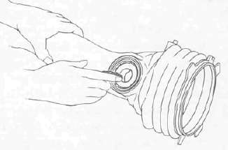
3. Remove the pad retaining clips.

1. Pad retaining clip
4. Pull out the pad retaining pins and remove the pad spring.
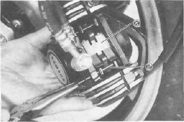
1 Pad retaining pin 2. Pad spring
5. Remove the brake pads.
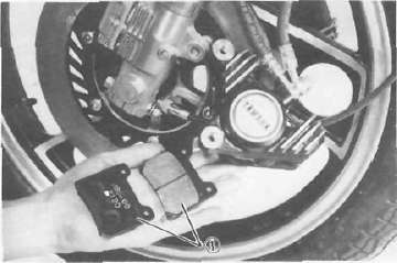
1. Brake pad
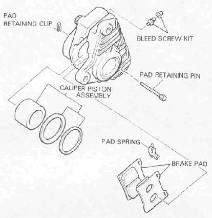
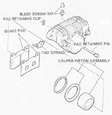
6. Install the new brake pads and shims. Before installing the pads, install the shim on the back plate which faces the caliper piston. Also replace the following parts if pad replacement is required.
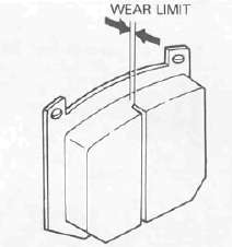
NOTE: Replace the pads as a set if either is found to be worn to the wear limit.
a. Pad retaining clips
b. Pad retaining pins
c. Pad spring
d. Brake pads
e. Shims

Caliper disassembly
1. Remove the caliper brake hose. Allow fluid in the caliper assembly to drain into a container.
2. Place the open hose end into the container and pump the old fluid out carefully.
3. Remove the caliper support bolts and the brake pads as described in the caliper pad replacement procedure.
4. Remove the caliper assembly from the caliper frame.
5. Remove the retaining ring and the dust seal.
6. Remove the piston.
CAUTION: Cover the piston with a rag. Use care so that the piston does not cause injury as it is expelled from the cylinder.
7. Remove the piston seal.
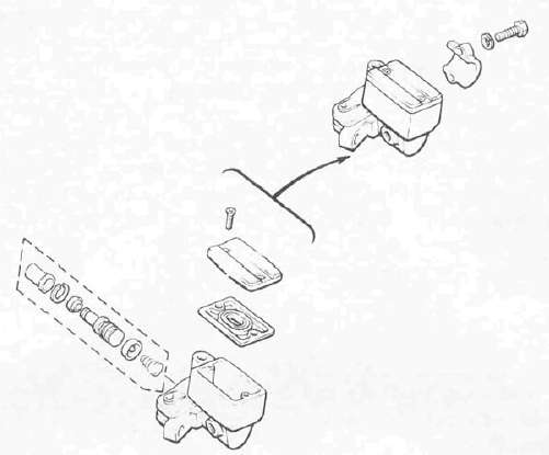
Master cylinder disassembly
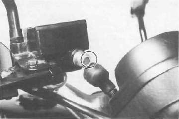
1. Front master cylinder a. Remove the brake light switch.
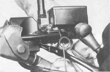
b. Remove the brake hose.
c. Remove the brake lever and spring.
d. Remove the master cylinder from the handlebar. Remove the reservoir cap and drain the remaining fluid.
e. Remove the master cylinder dust boot
f. Remove the snap ring.
g. Remove the master cylinder cup assembly. Note that the cylinder cups are installed with the larger diameter (lips) inserted first.
Brake inspection and repair
Recommended brake component
Replacement schedule: Brake pads; As required Piston seal, dust seal; Every two years Brake hoses; Every four years Brake fluid; Replace only when brakes are disassembled
1. Replace the caliper piston if it is scratched.
2. Replace any brake pad worn beyond limits. Always replace the brake pads as a set.
Wear limit:
Front and rear 0.5 mm (0.020 in)
See Caliper pad replacement procedure for a listing of the parts to be replaced when pads are replaced.
3. Replace piston and dust seals if damaged. Replace seals every two years.
4. Inspect master cylinder body. Replace if scratched. Clean all passages with new brake fluid.
5. Inspect the brake hoses. Replace every four years or immediately if cracked, frayed, or damaged.
6. Check for wear and deflection of disc.
Maximum deflection (front and rear):
0.15 mm (0.006 in) Minimum disc thickness:
Front: 7.0 mm (0.28 in)
Rear: 8.0 mm (0.32 in)
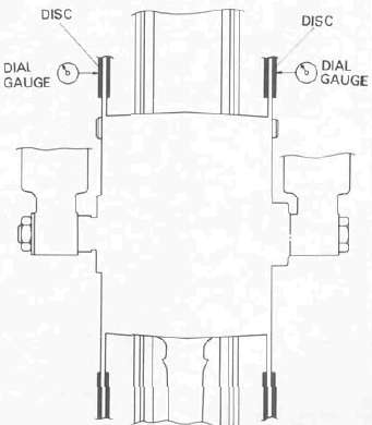
WARNING: If disc is worn beyond minimum thickness or deflection exceeds specified amount, replace disc.
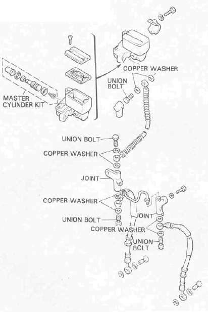
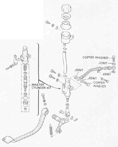
MASTER CYLINDER
Brake reassembly
1. All internal parts should be cleaned in new brake fluid only. Internal parts should be lubricated with brake fluid when installed.
2. Caliper reassembly
Replace the following parts whenever a caliper is disassembled: bleed screw and cap, piston seal, dust seal, and retaining ring.
a. Install the piston seal and piston. Place the caliper cylinder into the caliper frame.
b. Install the shims, brake pads, pad spring, pad retaining pins and the pad retaining clips.
c. Install the caliper assembly on the front fork (For front brake). Install the caliper assembly on the bracket (For rear brake).
NOTE: Apply a thread locking compound such as "LOCTITE" to the support bolts.
Caliper support bolt torque: 35 Nm (3.5 mkg, 25 ft-lb)
3. Attach the brake hoses.
Brake hose torque: 26 Nm (2.6 mkg, 19 ft lb)
4. Master cylinder reassembly
Reassemble master cylinder as shown in illustration.
Brake hose torque: (all brake union blots) 26 Nm (2.6 mkg, 19 ft-lb)
5. Brake disc assembly
If the brake disc has been removed from the hub or is loose, tighten the bolts.
Disc bolt torque: 20 Nm (20 m-kg, 14 ft-lb)
6. Air bleeding
NOTE: Bleed the brake system in order of the following steps.
1. Anti-dive unit
2. Front brake caliper
3. Rear brake caliper
WARNING: If the brake system is disassembled or if any brake hose has been loosened or removed, the brake system must be bled to remove air from the brake fluid. If the brake fluid level is very low or brake operation is incorrect, bleed the brake system.
Failure to bleed the brake system properly can result in a dangerous loss of braking performance.
a. Add proper brake fluid to the reservoir. Install the diaphragm, being careful not to spill or overflow the reservoir.
b. Connect the clear plastic tube of 4.5 mm (3/16 in) inside diameter tightly to the bleed screw. Put the other end of the tube into a container.
c. Slowly apply the brake lever or pedal several times. Pull in the lever (push down the pedal). Hold the lever or pedal in "on" position. Loosen the bleed screw. Allow the lever or pedal to travel slowly toward its limit When the limit is reached, tighten bleed screw. Then release the lever (or pedal).
d. Repeat step "c" procedure until all air bubbles are removed from system.
NOTE: If bleeding is difficult it may be necessary to let the brake fluid system stabilize for a few hours. Repeat the bleeding procedure when the tiny bubbles in the system settle out.
Brake disc installation
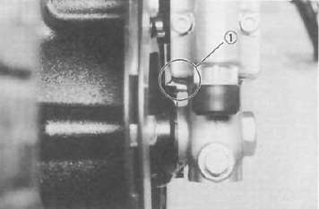
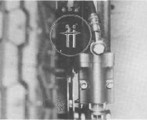
1. When installing the brake disc(s), the slots on the disc should be positioned as shown.
NOTE: Make sure the directions in which discs are installed. For this purpose an identification mark is stamped on the brake disc.
1. Slot 2. Identification mark (Rotating direction)
1. Slot 2 Identification mark (Rotating direction)
Tires
TiresTo ensure maximum performance, long service, and safe operation, note the following: Tire air pressure
Always check and adjust the tire pressures before operating the motorcycle.
WARNING: Tire inflation pressure should be checked and adjusted when the temperature of the tire equals the ambient air temperature. Tire inflation pressure must be adjusted according to total weight of cargo, rider, passenger, and accessories (fairing, saddlebags, etc. if approved for this model), and vehicle speed.
|
Basic weight: With oil and full fuel tank |
242 kg (534 lb) |
|
|
Maximum load |
194kg (428 lb) |
|
|
Cold tire pressure |
Front |
Rear |
|
Up to 90 kg (198 lb) load* |
226 kPa (2.3 kg/cm'. 32 psi) |
245 kPa (2.5 kg/cm2. 36 psi) |
|
90 kg (198 1b).-Maximum load |
245 kPa (2.5 kg/cm2, 36 psi) |
284 kPa (2.9 kg/cm2, 42 psi) |
|
High speed riding |
245 kPa (2.5 kg/cm2. 36 psi) |
284 kPa (2.9 kg/cm2. 42 psi) |
Load is the total weight of cargo, rider, passenger, and accessories.
WARNING: Proper loading of your motorcycle is important for the handling, braking, and other performance and safety characteristics of your motorcycle. Do not carry loosely packed items that can shift. Securely pack your heaviest items close to the center of the motorcycle, and destribute the weight evenly from side to side. Properly adjust the suspension for your load, and check the condition and pressure of your tires. NEVER OVERLOAD YOUR MOTORCYCLE. Make sure the total weight of the cargo, rider, passenger, and accessories (fairing, saddlebags, etc. if approved for this model) does not exceed the maximum load of the motorcycle. Operation of an overloaded motorcycle could cause tire damage, an accident, or even injury.
Inspection
Always check the tires before operating the motorcycle. If a tire tread shows crosswise lines (minimum tread depth), if the tire has a nail or glass fragments in it, or if the side wall is cracked, replace the tire.
|
Minimum tire tread depth (front and rear) |
1.0 mm (0.04 in) |
WARNING: It is dangerous to ride with a worn-out tire. When a tire thread begins to show lines, replace the tire immediately.

WARNING: This motorcycle is fitted with "V" range tires (for super high speed running). The following points must be observed in order for you to make fully effective use of these tires.
1. Never fail to use "V" range tires in tire replacement. "S" or "H" tires may have a danger of bursting at super high speeds.
2. Tires have a relatively low gripping on the road surface when new, so do not allow any new ones to be subjected to load from maximum speed until after approx. 100 km (60 mi.).
3. Before any high-speed runs, remember to give a sufficient warm-up to the tires.
4. Always use the correct tire inflation pressure according to the operating conditions.
Front Forks
Front Forks 
Removal and disassembly
WARNING: Securely support the motorcycle so it won't fall over when the front wheel and front forks are removed.
1. Remove the front wheel. Refer to "FRONT WHEEL"
2. Remove the windscreen assembley.
3. Remove the actuating piston housing securing bolts, and remove the actuating piston housing from the anti-dive valve assembly.

4. Remove the caliper cylinder securing bolts.
NOTE: Do not depress the brake lever when the wheel is off the motorcycle as the brake pads will be forced shut.

5. Remove the fork air valve cap and depress the valve until the air pressure escapes completely from the both forks.
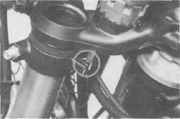
6. Remove the rubber cap from the top of the fork.
NOTE: Before loosen the fork pinch bolts, loosen the fork cap bolt.
1. Rubber cap
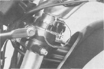
7. Loosen the fork pinch bolts in the handle crown and under bracket.
8. Remove the damper, air joint pipe bracket and circlip.

1. Damper 2. Air joint pipe 3. Circlip
9. Slide the inner fork tube out of the handle crown and under bracket Remove the front forks.

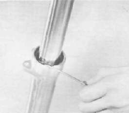
10. Remove the dust seal with a thin screwdriver. Take care not to scratch the inner fork tube. Discard the dust seal.

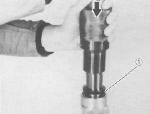
11. Remove the cap bolt and fork spring.
1. Cap bolt 2. Fork spring
12. Place an open container under the fork and turn the fork upside down and drain the oil.
NOTE: Do not remove the drain bolt from outer fork tube, the cylinder securing bolt can not be removed unless the drain bolt is in place.
13. Remove the anti-dive valve assembly from the bottom of the fork.

14. Remove the cylinder securing bolt from the bottom of the outer fork tube.
15. Remove the damper rod (cylinder complete) and rebound spring.
1. Damper rod (Cylinder complete) 2. Rebound spring
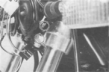
16. Remove the retaining clip and back-up ring from the outer fork tube.
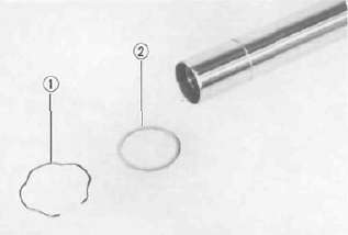
1. Retaining clip 2. Back-up ring
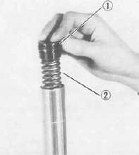
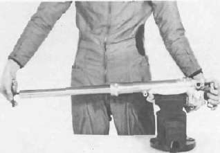
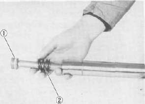
17. Hold the front fork outer tube in a vise horizontally. Put in the inner fork tube just before it bottoms out and then pull it back quickly.Repeat this step until the inner fork tube can be pulled out from the outer fork tube (usual 2 or 3 times). Then, the oil seal, seal spacer, guide bush, and slide bush all come out together, and remove the two valve springs, oil lock piece valve, and oil lock piece.
CAUTION: Don't bottom out the inner fork tube in the above step, or the oil lock piece valve and oil lock piece will be damaged.
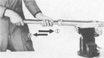
1. Put in slowly 2. Pull back quickly
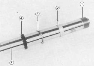
1. Slide bush 2. Guide bush 3. Seal spacer 4. Oil seal 5. Inner fork tube
Inspection
Clean and inspect all front fork components. Replace any worn or damaged components prior to reassembly.
1. Check the inner fork tube and replace if the tube is badly scratched or bent.
WARNING: Do not attempt to straighten a bent inner fork tube as this may dangerously weaken the tube.
2. Check the outer surface of the fork seal seat and outer surface of the back-up ring seat in the outer fork tube for damage. Replace the tube if for necessary.
3. Check the outer tube for dents. Replace the tube if for necessary.
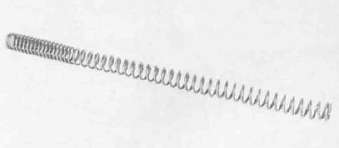
4. Check the free length of the fork spring.
Fork spring free length: 522.5 mm (20.6 in)
5. Check the 0-ring of the cap bolt air joint pipe bolt, and air joint cover. Replace any damaged 0-ring.
6. Check the damper rod for wear, damage, or contamination. Blow out all oil passages with compressed air. If it is worn or damaged, replace it.

7. Check the oil lock piece valve and oil
lock piece. Replace it, if damaged.
Reassembly
NOTE: In front fork reassembly, be sure to use following new parts.
Valve spring
Guide bush
Slide bush
Oil seal
Dust seal
1. Make sure all components are clean before reassembly.
2. Install the rebound spring to the damper rod.
3. Slide the damper rod into the inner fork tube from its top.
4. Fit the two valve springs, oil lock piece valve and oil lock piece in that order over the damper rod sticking out of the inner fork tube.
1. Damper rod 2. Oil lock piece valve 3. Valve spring
4. Oil lock piece
5. Insert the inner fork tube in the outer fork tube.
NOTE: For this insertion, mate the threaded end hole of the damper rod and the hole in the outer fork tube bottom end, and also mate the lower oil passage of the four in the oil lock piece and the lowest hole in the side of the outer fork tub.
6. Apply thread-locking compound such as LOCTITE to the cylinder securing bolt and install it. Torque the bolt to specification.
Tightening torque:
23 Nm (2.3 mkg, 17 ft-lb)
7. Install the anti-dive valve housing onto the front fork and secure it with bolts. Torque the bolts to specification.
NOTE: Before installing the anti-dive valve housing, install the O-rings around the front fork oil pasages.
Tightening torque:
7 Nm (0.7 mkg, 5.1 ft-lb)
8. Install the guide bush by pressing it in with special tool. Then, install the seal spacer into the outer fork tube.
1. Guide bush
9. Apply oil to the oil seal, and install the oil seal by pressing it in with special tool. Then, install the back-up ring and retaining clip.
NOTE: Before appling oil, tape the inner tube over its groove so that the groove edge will not damage the oil seal lip.
1. Oil seal
10. Install the dust seal and fork spring.
NOTE: When installing the fork springs, the greater pitch should be at the bottom. The main fork spring has a small coil diameter at the bottom.
11. Pour the specified amount of recommended fork oil into the inner fork tube.
Fork oil capacity (each fork): 286 ± 4 cm3 (10.1 ± 0.14 Imp oz, 9.67 ± 0.14 US oz) Recommended oil:
SAE 5W type SE motor oil or equivalent
12. After filling, slowly pump the forks up and down to distribute the oil and temporarily install the cap bolt.
13. Slide the fork into the under bracket.
14. Apply a light coat of lithium soap base grease to the O-rings in the air joint bracket. Install the circlip, air joint bracket and damper over the inner fork tube.
15. Slide the fork into the handle crown in the following way.
a. Make sure the projecting portion (stopper) of the air joint bracket is positioned correctly.
b. Fit the front fork by pushing it up until its top is flush with the handle crown top end. Holding the front in this position, temporarily tighten the pinch bolts with fingers.
16. Tighten the fork pinch bolts at the handle crown and under bracket. Then, tighten the cap bolt.
Tightening torque: Handle crown: 20 Nm (2.0 mkg, 14 ff-lb) Under bracket: 23 Nm (2.3 mkg, 17 ft-lb) Cap bolt: 23 Nm (2.3 mkg, 17 ft-lb)
1 7. Fit the fork with air using a manual air pump or other pressurized air supply.
Standard air pressure: 39.2 kPa (0.4 kg/cm2, 5.7 psi)
18. Install the air valve cap.
19. Install the caliper cylinder, the actuating piston housing and the front wheel. Refer to "FRONT WHEEL".
Tightening torque: Caliper cylinder: 35 Nm (3.5 mkg, 25 ft lb) Actuating piston housing: 5 Nm (0.5 mkg, 3.6 ft-lb)
Anti-Dive system
Anti-Dive systemSystem inspection
1. Apply the front brake for a few minutes and check to see if any brake fluid leaks out of the pipe joints, the master cylinder, or the actuating piston housing.
2. Check the fork for fork oil leakage.
3. Turn the anti-dive adjusting bolt to the maximum position.
4. Compress the front forks while applying the front brake. If the front forks are compressed easily, the anti-dive system may be damaged.
Removal
1. Release the air from the front fork by pressing the air valve pin.
2. Remove the drain screw from front fork and drain the fork oil.
3. Remove the brake hose from the actuating piston housing.

1. Actuating piston housing
4. Remove the bolts securing the actuating piston housing, and remove the housing from the anti-dive valve housing.
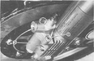
1 Securing bolt 2. Anti-dive valve hausing
5. Remove the anti-dive adjusting bolt cover.
CAUTION: The adjusting bolt can not be removed from its seat.
1. Adjusting bolt
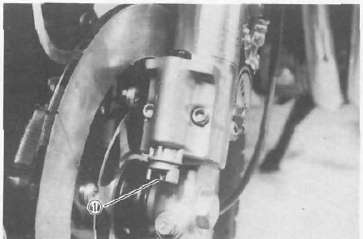
6. Remove the bolts securing the anti-dive valve assembly and remove the housing assembly from the front fork. Remove two O-rings from the front fork.
1. Anti-dive valve assembly 2. 0-ring
Inspection
NOTE: The anti-dive valve housing can not be disassembled so it must be replaced with a new one if the anti-dive valve malfunction is found.
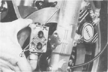
1. Remove the circlip and remove the actuating piston from the actuating piston housing.
CAUTION: Do not remove the O-ring from the actuating piston.

1. Circlip 2. Actuating piston
2. Check the piston, O-ring, and cylinder for wear, cracks, rust, and/or scrathces. If any damage is found, replace the actuating piston housing assembly.
3. Check the piston separator for cracks and replace if damaged.
4. Check the spring seat rivetted portion of the adjusting bolt for damage. Replace the adjusting bolt seat assembly if damgaed.
Assembly
1. Lubricate the actuating piston with clean brake fluid, and carefully insert the piston into the actuating piston housing cylinder until the shoulder of the piston is flush with the cylinder edge.
2. Install the washer and circlip.
3. Install the separator into the actuating piston housing.
4. Install new O-rings around the front fork oil pasages.
5. Install the anti-dive valve housing onto the front fork and secure it with bolts. Torque the bolts to the specification.
Tightening torque: 7 Nm (07 rrvkg, 5.1 ft-lb)
6. Install the actuating piston housing onto the anti-dive valve housing and secure it with two bolts. Torque the bolts to the specification.
Tightening torque: 5 Nm (0.5 mkg, 3.6 ft-lb)
7. Connect the brake hose to the actuating piston housing with the union bolt and copper washers. Torque it to the specification.
Tightening torque: 26 Nm (2.6 mkg, 19 ft-lb)
8. Pour the specified amount of front fork oil into the fork inner tube.
Front fork oil capacity (each leg): 286 ± 4 cm3 (10.1 ± 0.14 imp oz,
9.67 ± 0.14 US oz) Recommended oil: SAE 5W type SE motor oil or equivalent
9. Add proper brake fluid into the brake reservoir being careful not to spill or overflow.
10. Connect the clear plastic tube of 4.5 mm (0.18 in) in inside diameter tightly to the actuating piston housing bleed screw. Put the other end of the tube into a container.
11. Slowly apply the brake lever several times. Pull in the lever. Hold the lever in the "on" position. Loosen the bleed screw. Allow the lever to travel slowly toward its limit. When the limit is reached, tighten the bleed screw. Then release the lever.
12. Repeat the above step until ail air bubbles are removed from the brake line. It may be necessary to bleed the caliper cylinder in the same manner.
NOTE: If the bleeding is difficult it may be necessary to let the brake fluid in the system stabilize for a few hours and repeat the bleeding procedure.
13. Fill the fork with air using a manual air pump or other pressurized air supply.
Standard air pressure: 39.2 kPa (0.4 kg/cm2, 5.7 psi)
14. Adjust the anti-dive adjusting bolt. See Anti-Dive Adjustment.
WARNING: The anti-dive setting must be the same on both anti-dive units.
Steering Head
Steering Head 
Adjustment
See Steering Head Bearings for Steering head adjustment.
Removal
1. Remove the front wheel, front forks, windscreen, handlebars and meter assembly.
2. Remove the stem bolt and steering crown.

1 Steering stem bolt
3. Remove the lock washer, top fitting nut (ring nut) and rubber damper.

1. Lock washer

1. Top fitting nut

1. Rubber damper
4. Support the steering stem (under bracket) and remove the bottom fitting nut (ring nut).

5. Remove the bearings.
Inspection
1. Wash the bearings in solvent.
2. Inspect the bearings for pitting or other damage. Replace the bearings if pitted or damaged. Replace the races when bearings are replaced.
3. Clean and inspect the bearing races. Spin the bearings by hand. If the bearings are not smooth in their operation in the races, replace bearings and races.

Reassembly
1. Grease the bearings and races with wheel bearing grease.
2. Install the steering stem (under bracket) and bearings.
3. Install the bottom fitting nut. Tighten it to approximately 10 — 12 Nm (1.0 — 1.2 mkg, 7.2 ~~ 8.7 ft-lb). Do not over tighten it. Tighten the top fitting nut.
4. Continue reassembly in the reverse of disassembly order.
5. When assembly is complete, check the steering stem by turning it from lock to lock. If there is any binding or looseness, readjust the steering stem tightness.
Steering stem bolt torque: 110Nm (11.0 m-kg, 80 ft lb)
Rear Suspension (Swingarm and Shocks)
Rear Suspension (Swingarm and Shocks) 
Inspection
1. Remove the rear wheel and both shock absorbers. Grasp the swing arm and try to move it from side to side as shown. There should be no noticeable side play.

2. The swing arm is mounted on tapered bearings. Move the swing arm up and down as shown. The swing arm should move smoothly, without tightness, binding or rough spots that could indicate damaged bearings.

Adjustment
1. Measure the gap between the frame and the swing arm on the left and right sides. There should be not more than 1.6 mm (0.062 in) difference between the left and right gaps.
NOTE: It may be easier to inspect the gap with the rear wheel removed; however, such removal is not necessary.

LESS THAN 1.6 mm (0.062 in) DIFFERENCE BETWEEN A AND B GAPS.
2. If the left and right gaps differ by more than the limit [1.6 mm (0.062 in)] adjust as follows:
a. Remove the pivot shaft caps from the left and right sides of the swing arm.
b. Loosen both the left and right pivot shafts lock nuts.
c. Loosen the pivot shaft on the side of the greater swing arm/frame gap. Loosen only slightly (counterclockwise, approximately one-half turn). After loosening, tighten the opposite pivot shaft (clockwise) to 5 — 6 Nm (0.5 ~~ 0.6 m-kg, 3.6 - 4.3 ft lb).

1. Lock nut 2 Pivot shaft
d. Measure the gap again between the frame and the swing arm. If the left and right gaps are not within 1.6 mm (0.062 in) of each other, repeat step. c.
e. When the left and right gaps are adjusted properly, tighten the pivot shaft lock nut.
NOTE: Do not allow the pivot shaft to turn while tightening the lock nut
Pivot shaft lock nut torque: 100 Nm (10 mkg, 72 ft lb).
Removal
1. Remove the middle gear flange holding bolts.
2. Remove the rear wheel and shock absorbers. Remove the rear brake assembly.
3. Remove the final gear assembly.
4. Remove the swing arm pivot caps, the pivot shafts and the swing arm.
Inspection and lubrication
1. Remove the oil seals and the bearings. Inspect the bearings for pitting or other damage. Make sure that the bearings roll freely. If a bearing is damaged, both bearings and both sets of inner and outer bearing races should be replaced.
CAUTION: Do not use compressed air to spin the bearings dry. This causes damage to the bearing surfaces.
NOTE: When installing new bearings, grease liberally with lithium base, waterproof wheel bearing grease.
2. Always replace the grease seals when bearings are removed.
3. Examine the rubber boot for damage. Replace if damaged.

Installation
Installation of the swing arm can be accomplished by reversing the removal procedure. Observe adjustment procedures for obtaining equal frame/swing arm spacing.
CAUTION: A lock washer for left side pivot bolt must be replaced with a new one and the tab should be bent over along the bolt flat after tightening.
REAR SHOCK ABSORBER ("DE CARBON" SYSTEM) Handling notes
WARNING: This shock absorbers are provided with a separate type tank filled with high-pressure nitrogen gas. To prevent the danger of explosion, read and understand the following information before handling the shock absorbers.
The manufacturer can not be held responsible for property damage or personal injury that may result from improper handling.
1. Never tamper or attempt to disassemble the cylinder or the tank.
2. Never throw the shock absorber into an open flame or other hight heat. The shock absorber may explode as a result of nitrogen gas expansion and/ or damage to the unit.
3. Be careful not to damage any part of the gas tank. A damaged gas tank will impair the damping performance or cause a malfunction.
4. Take care not to scratch the contact surface of the pistion rod with the cylinder; or oil could leak out.
5. When scrapping the shock absorber, follow the instructions on disposal.
Notes on disposal
Before disposing the shock absorber, be sure to extract the nitogen gas. To do so, drill a 2 — 3 mm (0.08 ~ 0.12 in) hole through the tank at a position 25 ~~ 30 mm (1.0 — 1.2 in) from the bottom end of the tank. At this time, wear eye protection to prevent eye damage from escaping gas and/or metal chips.

Removal and reinstallation
1. Remove the seat and side covers (Left and right).
2. Remove the rear stay and rear fairing.

3. Remove the muffler securing bolts and remove the mufflers.
4. Remove the rear shock absorber mounting nuts and standing handle securing bolt. Then, pull out the rear shock absorber from the frame.

5. For reinstallation, reverse the procedure for removal. When installing, observe the specified tightening torque.
Upper (Left and right sides): 30 Nm (3.0 nrvkg. 22 ft-lb)
Bottom (Left and right sides): 30 Nm (3.0 mkg. 22 ft-lb)
Rear stay: 23 Nm (2.3 mkg. 17 ft lb)
Inspection
1. Check the rod. If it is bent or damaged, replace the shock absorber.
2. Check for oil leakage. If oil leakage is evident replace the shock absorber.
3. Operate shock absorber rod to check damping. There should be not noticeable damping as the shock extends.

Cable and Fittings
Cable and FittingsCable maintenance
NOTE: See Maintenance and Lubrication intervals charts. Cable maintenance is primarily concerned with preventing deterioration through rust and weathering and providing proper lubrication to allow the cable to move freely within its housing.
WARNING: Cable routing is very important. For details of cable routing, see the cable routing diagrams at the end of this manual. Improperly routed or adjusted cables may make the motorcycle unsafe for operation.
1. Remove the cable.
2. Check for free movement of cable within its housing. If movement is obstruced, check for fraying or kinking of the cable strands. If damage is evident, replace the cable assembly.
3. To lubricate the cable, hold it in a vertical position. Apply lubricant to the uppermost end of cable. Leave it in the vertical position until lubricant appears at the bottom. Allow any excess to drain and reinstall the cable.
NOTE: Choice of lubricant depends upon conditions and preferences. However, a semi-drying chain and cable lubricant will perform adequately under most conditions.
Throttle maintenance
1. Remove the Phillips head screws from throttle housing assembly and separate the two halves of housing.
2. Disconnect the cable end from the throttle grip assembly and remove the grip assembly.
3. Wash all parts in a mild solvent and check all contact surfaces for burrs or other damage. (Also clean and inspect right-hand end of the handlebar.)
4. Lubricate all contact surfaces with a light coat of lithium soap base grease and reassemble.
NOTE: Tighten the housing screws evenly to maintain an even gap between the two halves.
5. Check for smooth throttle operation and quick spring return when released and make certain that the housing does not rotate on the handlebar.
Shaft Drive
Shaft DriveSpecial Tools and Troubleshooting
Special Tools and TroubleshootingThe following special tools are not available but can be constructed for the final gear disassembly and assembly:
PRESS TOOL NO. 1

PRESS TOOL NO. 2

GEAR CASE HOLDING TOOL


Troubleshooting
1. The following conditions may indicate damaged shaft drive components:
|
Symptoms |
Possible damaged areas |
|
1. A pronounced hesitation or "jerky" movement during acceleration, deceleration, or sustained speed. (This must not be confused with engine surging or transmission characteries). |
A. Damage to bearings. |
|
B. Improper gear lash. |
|
|
C. Gear tooth damage. |
|
|
2. A "rolling rumble" noticeable at low speed; a high-pitched whine; a "clunk" from a shaft drive component or area. |
D. Drive flange/universal joint bolts loose. |
|
3. A locked-up condition of the shaft drive mechanism; no power transmitted from engine to rear wheel. |
E. Broken drive-shaft. |
|
F. Disconnected flange/universal joint connection. |
|
|
G. Broken gear teeth. |
|
|
H. Seizure due to lack of lubrication. |
|
|
I. Small foreign object lodged between moving parts. |
NOTE: Damage areas A, B, and C above may be extremely difficult to diagnose. The symptoms are quite subtle and difficult to distinguish from normal motorcycle operating noise. If there is reason to believe component(s) are damaged, remove component(s) for specific inspection.
2. Inspection notes
a. During coasting, accelerating or decelerating, the "rolling rumble" will increase with rear wheel speed, not engine or transmission gear speeds. However, such noise may also be due to wheel bearings.
b. Noise that varies with acceleration and deceleration: Following incorrect reassembly, a condition of too-little gear lash may produce a whine during deceleration.
CAUTION: Too-little gear lash is extremely destructive to gear teeth. If a test ride following reassembly indicates this condition, stop riding immediately to minimize damage to gears.
c. A slight "thunk" must be distinguished from normal motorcycle operation. It will be most noticeable at low speed and could indicate broken gear teeth.
WARNING: If broken gear teeth are suspected, stop riding immediately. This condition could lead to locking-up of the shaft drive assembly and result in harm to a rider.
d. If the drive flange/universal joint bolts are slightly loose, a "clunk" may be felt when slowly taking off, or when changing from slow acceleration to slow decelration. At high speed this will result in vibration.
WARNING: Do not continue riding a motorcycle suspected of having loose flange/universal joint bolts. The components may break, causing injury to a rider.
3. Troubleshooting chart
Where Basic Conditions "a" and "b" above exist, consider the following chart:
|
Elevate and spin front wheel. Feel for wheel bearing damage. |
Yes |
Replace wheel bearing. (See CHAPTER 5 "FRONT WHEEL") |
|
I No |
||
|
Check rear wheel. Feel for bearing damage. |
No |
Rear wheel bear-inbgs and shaft drive bearings probably not damaged. Repeat test or remove individual components. |
|
Yes |
||
|
Remove rear wheel. Check for wheel bearing damage. |
Yes |
Repelace rear wheel bearing. (See "REAR WHEEL" section in this chapter.) |
|
No |
||
|
Remove drive shaft components. |
4. Oil leak inspection
If a shaft drive component is suspected of leaking oil, first thoroughly clean the entire motorcycle. The spparent location of an oil leak on a dusty motorcycle may be misleading. Dry the motorcycle and apply a leak-localizing compound or a dry-powder spray that will limit the flow of any leaking oil. Operate the motorcycle prepared in this way for the distance necessary to precisely locate the leak. There are the possibilities that a component housing may have been damaged by road debris or an accident, or a gasket or seal may be cracked or broken. However, on new or nearly new motorcycle an apparent oil leak may be the result of a rust-preventive coating or excess assembly lubrication of seals. Always clean the motorcycle and recheck the suspected location of any apparent leakage.

5. Checking drained oil
Whenever a problem is suspected in either the middle or final gear assemblies, drain and inspect the oil. Metal particles on the drain plug or in the oil could indicate a bearing seizure or other problem in the component. However, a small amount of metal particles in the oil is normal.
Final gear Removal and adjustment
Final gear Removal and adjustment 
Final gear removal
1. Remove the rear axle and left shock absorber. Remove the rear wheel (see "REAR WHEEL" section in this chapter).
2. Remove the 4 nuts holding the final drive unit to the swing arm.
3. Remove the final gear assembly.
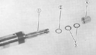
4. Remove the circlips, plate washer and oil seal. Then pull out the drive shaft.
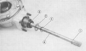
1. Circlip 2. Plate washer 3. Oil seal 4. Drive shaft
Gear lash check and adjustment
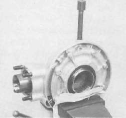
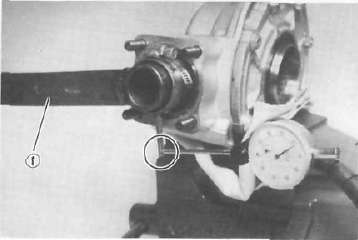
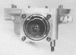
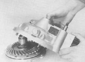
1. Secure the gear case in a vice or other support.
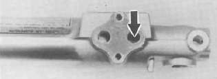
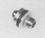
2. Remove the drain plug from the final gear case. Then, install a specified size of bolt (as shown) into the drain plug hole. Finger-tighten the bolt until it holds the ring gear.
NOTE: The bolt should not be over tightened, finger tight is sufficient.

3. Install the final gear lash measurement tool on the gear coupling.
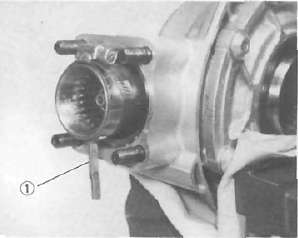
1. Gear lash measurement tool (Final gear)
4. Mount a dial gauge against the lash measurement tool at the scribed mark (60 mm (2.36 in) from the center of the shaft).
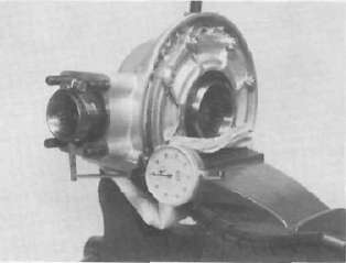
5. Use the special wrench to gently rotate the gear coupling back and forth. Note the lash measurement on the dial gauge.
Final gear lash: 0.25 — 0.50 mm (0.010 — 0.020 in) When using the measurement tool. 0.1 — 0.2 mm (0.004 — 0.008 in) Actual gear lash on the final gear teeth
1. Middle and final gear noising tool
6. If the gear lash exceeds the specified limits, adjust as follows.
a. To reduce gear lash, increase the ring gear shim.
b. To increase gear lash, reduce ring gear shim.
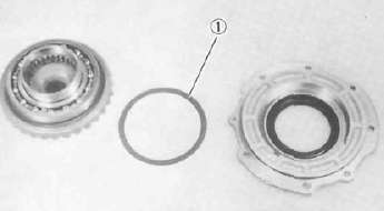
1. Ring gear shlim
c. If it is necessary to increase the ring gear shim by more than 0.1 mm (0.004 in) reduce the thrust washer thickness by 0.1 mm (0.004 in) for each 0.1 mm (0.004 in) of ring gear shim increase and if it is necessary to reduce shim by more than 0.1 mm (0.004 in), reverse above procedure.
Final gear Disassembly and Reassembly
Final gear Disassembly and ReassemblyFinal gear disassembly
1. Remove the nuts and bolts holding the bearing housing.
2. Remove the ring gear assembly and thrust washer from the final gear case.

3. Remove the self-locking nut from drive pinion by using the holding tool (special tool) and remove the coupling.
1. Middle and final gear holding tool
4. Remove the drive pinion bearing retainer with the retainer remover (special tool).
CAUTION: The drive pinion bearing retainer nut is left hand threads. Turn the retainer nut clockwise to loosen.
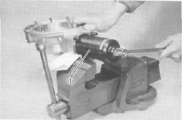
1. Drive pinion bearing retainer remover
5. Remove the drive pinion and bearing with the slide hammer and adapter (special tool).
CAUTION: This drive pinion removal should be performed only if gearing replacement is necessary. Do not re-use bearings or races after removal.

1. Slide hammer 2. Crank installer adapter
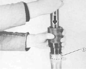
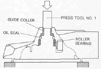
6. Remove the guide coller, oil seal, and roller bearing from the main housing by using the press tool No. 1 (special tool) and a press. Use an appropriate supports for the main housing during this operation. The roller bearing may be reused if undamaged. Do not re-use oil seal.
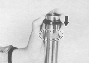
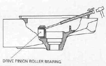
7. Rear drive pinion roller bearing; removal of this bearing is difficult and seldom necessary. Heat the bare housing to 150°C (302°F). Use an appropriately shaped punch to remove the roller bearing outer race. Remove the inner race from the drive pinion-
Final gear reassembly
1. Install the new rear drive pinion roller bearing. Heat the bare bearing to 150°C (302°F) and use an appropriately adapter to install the roller bearing outer race. Install the inner race onto the drive pinion.
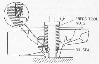

2. Using the press tool No. 2 (special tool) and a press, install the guide coller, new oil seal, and roller bearing into the main housing in that order.
NOTE: The removed roller bearing can be used if undamaged; however, we recommend replacement with a new one.
3. Final drive/ring gear positioning
NOTE: When the following part(s) is replaced with new one(s), gear positioning is necessary:
a. Final gear
b. Ring gear bearing housing
c. Bearing(s)
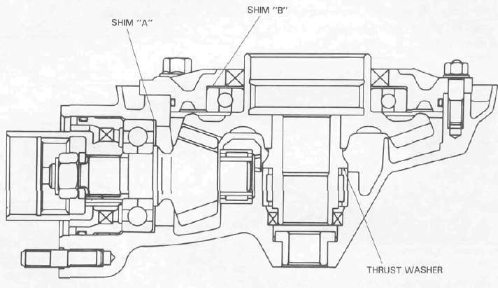
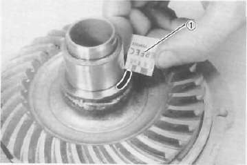
a. The shim thickness "A" necessary for the drive pinion gear positioning can be calculated from the informations found on the final gear case and on the drive gear end.
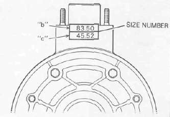
To fined shim thickness "A" use the formula:
A = a - b
Where: a =a numeral (usually a decimal number) on the gear near the tooth and either added to or detracted from the nominal size "84". b =a numeral on the gear case appearing as a whole figure (ie. 83.50).
Example:
1) If the pinion gear is marked "+01" ....: "a" is 84.01.
2) If the gear case is marked "83.50".
A = 84.01 - 83.50
A = 0.51
Then the necessary shim thickness is 0.51 mm.
Shim sizes are supplied in the following thicknesses:
0.15 mm, 0.30 mm, 0.40 mm, 0.50 mm, 0.60 mm.
Because the shims can only be selected in 0.05 mm increments the following
chart should be used when encountering last digits that are not 5 or zero (0):
|
Last digits |
Rounding |
|
0, 1.2 |
0 |
|
3, 4, 5, 6. 7 |
5 |
|
8, 9 |
10 |
Shim thickness: 0.50 mm
b. The shim thickness "B" necessary for the ring gear positioning can be calculated from the informations found on the final gear case, ring gear, and bearing.
To find shim thickness "B" use the formula:
B = c + d-(e + f)
Where:
c = a numeral on the gear case appearing as a whole figure (ie. 45.52)
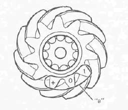
d = a numeral (usually a decimal number) on the outside of the ring gear bearing housing and added to the nominal size "3".
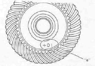
e = a numeral (usually a decimal number) on the inside of the ring gear and; either added to or detracted from the nominal size "35.40".
f = a bearing thickness (considered constant)
Distance "f" = 13.00 mm
Example:
1) If the gear case is marked "45.52".
2) If the ring gear bearing housing is marked "35"....."d" is 3.35.
3) If the ring gear is marked "+01" .....
"e" is 35.40 + 0.01 = 35.41.
4) "f" is 13.00.
B = c + d-(e + f)
B = 45.52 + 3.35 - (35.41 + 13.00)
8 = 48.87 - (48.41)
B = 0.46
Then the necessary shim thickness is 0.41 mm.
NOTE: Use the chart for the drive pinion shim to select the ring gear shim size.
Shim thickness: 0.40 mm
4. Install the drive pinion gear with the proper size of shim(s) and secure it with the bearing retainer nut with the drive pinion bearing retainer remover (special tool).
NOTE: The bearing retainer nut is left hand threads;
turn the nut to counterclockwise to tighten.
Tightening torque: 110 Nm (11.0 mkg, 80 ftlb)
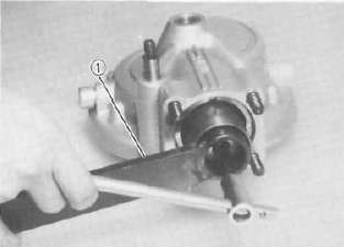
5. Install the ring gear assembly without the thrust washer. Adjust the gear lash (refer to "Gear lash check and adjustment").
6. Place four pieces of "PLASTIGAGE" between the originally fitted thrust washer and ring gear.
7. Install the gear case onto the ring gear assembly and tighten the nuts and bolts with the specified torque.
Tightening torque:
Bolt/Nut: 23 Nm (2.3 mkg, 17 ftlb)
NOTE: Do not turn the drive pinion/ring gear when measuring clearance with "PLASTIGAGE".
8. Remove the ring gear assembly and determine the clearance by measuring the width of the flattened "PLASTIGAGE".
Ring gear thrust clearance:
0.1 - 0.2 mm (0.004 - 0.0078 in)
1. PLASTIGAGE
9. If the clearance exceeds the specification above, replace the thrust washer to obtain the proper clearance.
Drive Shaft / Joint
Drive Shaft / Joint 
Removal
1. Remove the rear wheel.
2. Remove the final gear case assembly.
3. Remove the drive shaft.
4. To remove the universal joint, it is necessary to remove the swing arm. Remove the universal joint assembly.
Inspection
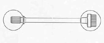
1. Drive shaft
Inspect the shaft splines for wear and/or damage. If excessive, replace the drive shaft
NOTE: When installing the drive shaft lubricate splines with molybdenum disulfied grease.
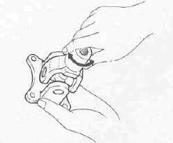
2. Universal joint
a. There should be no noticeable play in the universal joint bearings. If there is any play in the bearing, replace the universal joint assembly.
b. Move the universal joint up and down and from side to side. The universal joint should move smoothly. Without tightness, binding or rough spots that could indicate damaged bearings. If damaged, replace the universal joint assembly.
Reinstallation
When installing the drive shaft and the universal joint reverse the removal procedure. Note the following points:
1. Lubricate the shaft splines with molybdenum disulfied grease.
2. Tighten the universal joint securing bolts and final gear case securing nuts with the specified torque:
Final gear case:
42 Nm (4.2 mkg, 30 ft lb) Universal joint:
44 Nm (4.4 mkg, 32 ft-lb)