Chapter 8, APPENDICES
- Read more about Chapter 8, APPENDICES
- Log in to post comments
COOLING SYSTEM
3 Main switch
4 Fuse "FAN" (10A)
5 Thermo switch
6 Fan motor
18 Temperature meter
19 Thermo unit
35 Fuse "SIGNAL" (15A)
48 Battery
49 Fuse "MAIN" (30A)
SWITCHES
Use Pocket Tester (90890-03112) on "Ohm x 1" scale to check the switches. Replace any "shorted" or opened element.
Main Switch
|
Switch position |
IGNITION SYSTEM
3 Main switch
7 Fuse "IGNITION" (10A)
8 "ENGINE STOP" switch
9 Pickup coil
10 T.C.I, unit
11 Ignition coil (#2, #3)
12 Ignition coil (#1, #4)
13 Sidestand relay
48 Battery
49 Fuse "MAIN" (30A)
CHARGING SYSTEM
1 A.C. Generator
2 Rectifier/Regulator
3 Main switch
48 Battery
49 Fuse "MAIN" (30A)
STARTER MOTOR
ELECTRIC STARTING SYSTEM
ELECTRICAL COMPONENTS 1

1 Ignition coil
2 Thermo switch
3 Thermo unit
4 Main switch
5 Sidestand switch
6 Battery
7 T.C.I, unit
8 Rectifier/Regulator
9 Oil level switch
10 Rear brake switch
11 Neutral switch
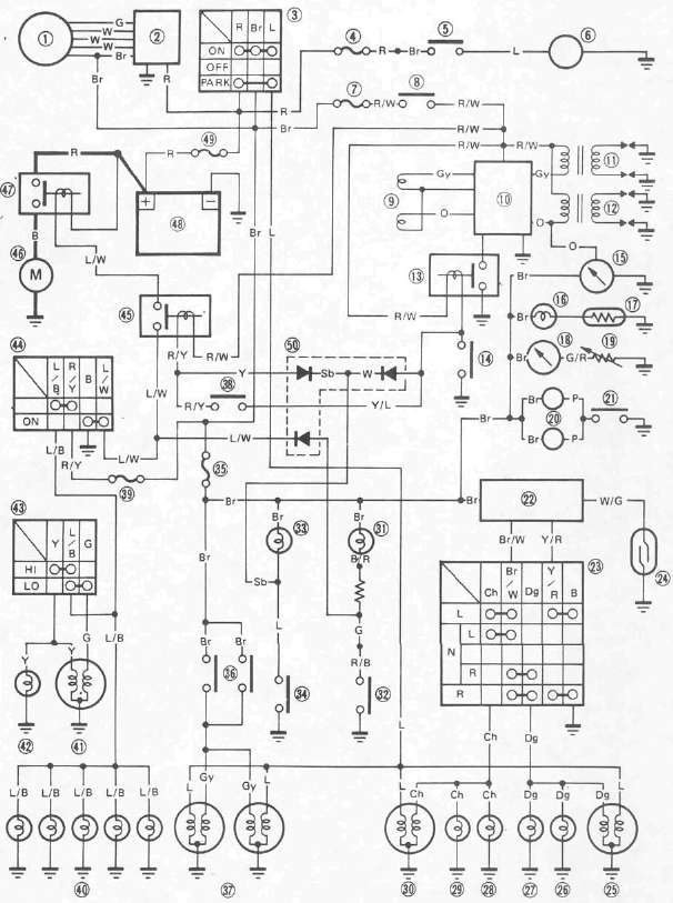
XJ750XS CIRCUIT DIAGRAM
CABLE MAINTENANCE
NOTE:
See "Maintanance and Lubrication" intervals charts. Cable maintenance is primarily concerned with preventing deterioration and providing proper lubrication to allow the cable to move freely within its housing. Cable removal is straightforward and uncomplicated. Removal is not discussed within this section.

