F. Cylinder
1. Inspect the cylinder walls for scratches. If vertical scratches are evident, the cylinder wall should be rebored or the cylinder should be replaced.
2. Measure cylinder wall wear as shown. If wear is excessive, compression pressure will decrease. Rebore the cylinder wall and replace the piston and piston rings. Cylinder wear should be measured at three depths with a cylinder bore gauge. (See illustration.)
|
|
Standard |
Wear Limit |
|
Cylinder bore |
63.00 mm (2.480 in) |
63.10 mm (2.484 in) |
|
Cylinder taper |
— |
0.05 mm (0.002 in) |
|
Cylinder out-of-round |
— |
0.01 mm (0.0004 in) |
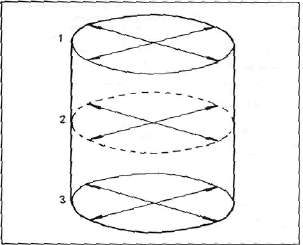
If the cylinder wall is worn more than the wear limit, it should be rebored.
G. Piston and Piston Rings
1. Piston
a. Measure the outside diameter of the piston at the piston skirt. Measurement should be made at a point 7.5 mm (0.3 in) above the bottom edge of the piston. Place the micrometer at right angles to the piston pin.
|
Standard |
63.00 mm (2.480 in) |
|
Oversize 1 |
63.25 mm (2.490 in) |
|
Oversize 2 |
63.50 mm (2.500 in) |
|
Oversize 3 |
63.75 mm (2.510 in) |
|
Oversize 4 |
64.00 mm (2.520 in) |
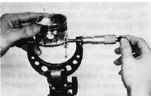
a. 7.5 mm (0.3 in)
b. Determine piston clearance as follows:
Minimum bore measurement
— Maximum piston measurement * Piston clearance
EXAMPLE:
63.0 mm (2.4803 in)
- 62.96 mm (2.4787 in) = 0.04 mm (0.0016 in)
Piston clearance
Piston clearance:
Standard: 0.030^ 0.050 mm (0.0012^ 0.0020 in)
Service limit: 0.1 mm (0.0039 in)
c. Piston ring/ring groove fit must have correct clearance. If the piston and ring have already been used, the ring must be removed and the ring groove cleaned of carbon. The ring should then be reinstalled. Use a feeler gauge to measure the gap between the ring and the land.
|
Side clearance |
Top |
0.03- 0.07 mm (0.0012- 0.0028 in) |
|
2nd |
0.02-0.06 mm (0.0008- 0.0024 in) |

1. Feeler gauge
2. Piston ring
a. The oversize top and middle ring sizes are stamped on top of the ring.
|
Oversize 1 |
0.25 mm (0.0098 in) |
|
Oversize 2 |
0.50 mm (0.0197 in) |
|
Oversize 3 |
0.75 mm (0.0295 in) |
|
Oversize 4 |
1.00 mm (0.0394 in) |
b. The expander spacer of the bottom ring (oil control ring) is color-coded to identify sizes.
The color mark is painted on the expander spacer.
|
Size |
Color |
|
Oversize 1 |
Brown |
|
Oversize 2 |
Blue |
|
Oversize 3 |
Black |
|
Oversize 4 |
Yellow |
c. Push the ring into the bore and check end gap clearance with a feeler gauge.
NOTE:
The end gap on the expander spacer of the oil control ring is unmeasurable. If the oil control ring rails show excessive gap, all three components should be replaced.
|
|
||
|
|
Standard |
Limit |
|
Top/2nd ring |
0.15 — 0.35 mm (0.006- 0.014 in) |
1.0 mm (0.039 in) |
|
Oil control (Rails) |
0.3-0.9 mm (0.012-0.035 in) |
1.5 mm (0.059 in) |
H. Piston Pin
1. Apply a light film of oil to pin. Install in connecting rod small end. Check for play. There should be no noticeable vertical play. If play exists, check connecting rod small end for wear. Replace pin and connecting rod as required.
2. The piston pin should have no noticeable free play in piston. If the piston pin is loose, replace the pin and/or the piston.
- Printer-friendly version
- Log in to post comments