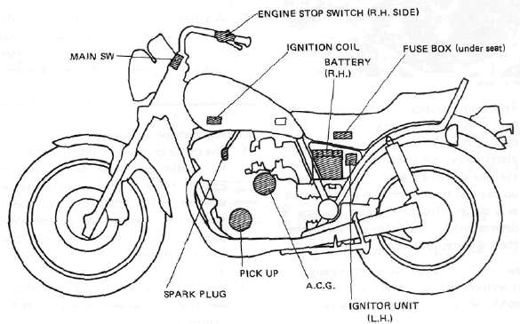
E. IGNITION SYSTEM

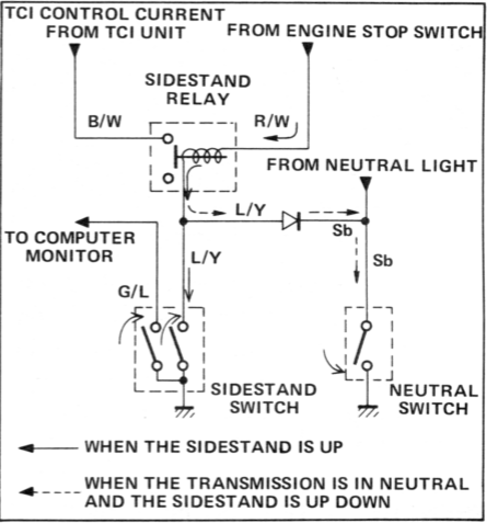
Above circuit diagram shows only ignition circuit in wiring diagram.
Description
This model is equipped with a battery operated, fully transistorized, breakerless ignition system. By using magnetic pickup coils, the need for contact breaker points is eliminated. This adds to the dependability of the system by eliminating frequent cleaning and adjustment of points and ignition timing. The TCI (Transistor Control Ignition) unit incorporates an automatic advance circuit controlled by signals generated by the pickup coil. This adds to the dependability of the system by eliminating the mechanical advancer. This TCI system consists of two units; a pickup unit and an ignitor unit.
NOTE:
The ignition circuit can be operated only when the sidestand is up (the sidestand switch is on) or the transmission is in neutral.
Operation
The TCI functions to the same principle as a conventional DC ignition system with the exception of using magnetic pickup coils and a transistor control box (TCI) in place of contact breaker points.
1. Pick-up unit

1. Pick-up coils
The pickup unit consists of two pickup coils and a flywheel mounted onto the crankshaft. When the projection on the flywheel passes a pickup coil, a signal is generated and transmitted to the ignitor unit. The width of the projection on the flywheel determines the ignition advance.
2- Ignitor unit

This unit controls when form, duty control, switching, electronic ignition advance, etc. They duty control circuit reduces electrical consumption by controlling the duration of the primary ignition current.
The ignitor unit also has a protective circuit for the ignition coil. If the ignition switch is on and the crankshaft is not turning, the protective circuit interrupts the current flow to the primary coil after a few seconds. When the crankshaft is turning, however, the ignitor unit sends current to the primary coil.
CAUTION:
Do not run the engine without any spark plug cap(s) in place. Due to the high secondary voltage, it is possible to damage the internal insulation of the secondary coil.
3. Sidestand relay
The sidestand relay operates by shorting the TCI control current. When the side-stand is down, the sidestand relay is closed, and the TCI control current is grounded through the sidestand relay. Thus, the engine will not run with the sidestand down unless the transmission is in neutral.
D. Troubleshooting/Inspection
1. The entire ignition system can be checked for misfire and weak spark using the Electro Tester. If the ignition system will fire across a sufficient gap, the entire ignition system can be considered good. If not, proceed with individual component tests until the problem is found.
a. Warm up engine thoroughly so that all electrical components are at operating temperature.
b. Stop the engine and connect the tester as shown.

c. Start the engine and increase the spark gap until misfire occurs. (Test at various r/min between idle and red line.)
Minimum spark gap: 6 mm (0.24 in)
CAUTION:
Do not run engine in neutral above 6,000 r/min for more than 1 or 2 seconds.
2. If the ignition system should become inoperative, the following troubleshooting aids will be useful.
| Check entire ignition for connections |
---------------> Poor connection |
Correct |
|
▼ OK ▼ |
||
| Check battery for voltage and specific gravity |
---------------> Low voltage & specific gravity |
Recharge battery |
|
▼ OK ▼ |
||
| Check fuse and fuse connections | ---------------> Weak connection or open circuit |
Correct connection or replace fuse |
|
▼ OK ▼ |
||
| Check resistance of ignition coil {primary and secondary) Primary: 2.5 Ω ± 10% at 20°C (68°F) Secondary: 11KΩ ± 20% at 20°C(68 F) |
---------------> If other than specified |
Replace ignition coil |
|
▼ OK ▼ |
||
| Check pick-up coils for resistance Pick-up coil: 700 Ω ± 20% at 20°C (68°F) |
---------------> If other than specified |
Replace pick-up coil assembly |
|
▼ OK ▼ |
||
| TCI unit is faulty, replace unit |
3. Ignition coil
a. Coil spark gap test.
1) Remove the fuel tank and disconnect the ignition coil from wire harness and spark plugs.
2) Connect the Electro Tester as shown.

3) Connect fully charged battery to tester.
4) Turn on spark gap switch and the increase gap to maximum unless misfire occurs first.
Minimum spark gap: 6 mm (0.24 in)
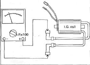
b. Direct current resistance test. Use a pocket tester or equivalent ohmmeter to determine resistance and continuity of primary and secondary coil windings.
Standard value:
Primary coil resistance:
2.5Ω ± 10% at 20°C (68°F)
Secondary coil resistance:
11 KΩ ± 20% at 20% (68°F)
Primary coil check

Secondary coil check
4. Spark plug
The life of a spark plug and its discoloring vary according to the habits of the rider. At each periodic inspection, replace burned or fouled plugs with new ones of the specified type. It is actually economical to install new plugs often since it will tend to keep the engine in good condition and prevent excessive fuel consumption.
a. Inspection
1) Inspect and clean the spark plug every 4,000 km (2,500 mi) and replace after initial 13,000 km (8,000 mi).
2) Clean the electrodes of carbon and adjust the electrode gap to the specification.
b. Installation
Be sure to use the proper reach, type and electrode gap plug(s) as a replacement to avoid overheating, fouling or piston damage.
Type:BP7ES (NGK) or W22EP (ND)
Electrode gap:0.7 - 0.8 mm (0.028 - 0.031 in)
Tightening torque:2.0 m-kg (14.5 ft-lb)
Sidestand relay inspection
1. Open the seat, and remove the fuel tank.
2. Remove the sidestand relay from the frame, and disconnect the connector.

1. Sidestand relay
3. Check the resistance of the relay coil windings with the pocket tester. If the resistance is not within specification, replace the relay.

4. Check the relay contact breaker points with the pocket tester and a 12 bolt battery. Connect the leads as shown in the illustration. If the resistance readings do not equal those shown in the illustration, replace the relay.

1. When the battery is connected.
2. When the battery is disconnected.
3. 12 volt battery
- Printer-friendly version
- Log in to post comments