FRONT FORK

CYLINDER SECURING BOLT
Removal And Disassembly
WARNING:
Securely support the motorcycle so there is no danger of it falling over.
1. Disconnect the speedometer cable. Remove the brake caliper and the front wheel. Remove the front fender.
2. Remove the rubber cap from the top of each fork.
3. Keep the air valve open by pressing it for several seconds so that the air can be let out of the inner fork tube.

4. The spring seat and fork spring are retained by a stopper ring (spring wire circlip). It is necessary to depress the spring seat and fork spring to remove the stopper ring. Remove the stopper ring by carefully prying out one end with a small screwdriver.

5. Place an open container under each drain hole. Remove the drain screw from each outer tube.
6. Loosen the pinch bolts on the upper and lower brackets, and remove the forks.
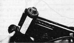
7. Remove the cylinder securing bolt from the bottom of the fork assembly. Hold the inner tube with the front-fork-cylinder holder. Pull the inner fork tube from the outer fork tube.

8. Remove the retaining clip from the outer fork tube, and pry out the fork seal. Be careful not to damage the fork tube surface.


Inspection
- Examine the inner fork tube. If the tube is severely scratched or bent, it should be replaced
WARNING:
Do not attempt to straighten a bent fork tube; this may dangerously weaken the tube.
2. Inspect the outer surface of the fork seal seat in the outer fork tube. If this surface is damaged, replace the outer fork tube. If it is not damaged, replace the fork seal.
3. Check the outer fork tubes for dents. Replace the tube if it is dented.
4. Check the free length of the springs.
Fork spring free length: 467 mm (18.39 in)
5. Check the o-ring on the spring seat. If it's damaged, replace it.

Assembly
1. Make sure all components are clean before assembly. Always install a new fork seal. Do not reuse a seal.
2. Apply oil to the fork seal, and install the fork seal by pressing it in with a large socket. Install the retaining clip.
3. Install the inner fork tube into the outer fork tube.
4. Apply Loctite® Stud N' Bearing Mount (red) to the cylinder securing bolt, and install the bolt and a copper washer into the outer fork tube. Torque the bolt to specification.
TIGHTENING TORQUE: 2.0m-kg (14.5ft-lb)
5. Reinstall the spring seat and fill the fork with air using a manual air pump.
CAUTION:
Always use a new stopper ring (spring wire circlip)
Maximum air pressure: 1.2 kg/cm1 (17 psi) Do not exceed this amount
Air pressure adjustment
1. Elevate the front wheel by placing the motorcycle on the center stand.
NOTE:
When checking and adjustment the air pressure, there should be no weight on the front end of the motorcycle.
2. Remove the rubber caps from each fork.
3. Using an air gauge, check and adjust the air pressure.
Increase air pressure — cause initial load to increase, and
absorber becomes hard.
Decrease air pressure — cause initial load to decrease, and
absorber becomes soft.
To increase:
Fill the air using a manual air pump.
To decrease:
Release the air by pushing the valve pin.

1. Air gauge
Standard air pressure: 0.4 kg/cm3 (5.7 psi)
Maximum air pressure: 1.2 kg/cm1 (17 psi)
Minimum air pressure: Zero
*Never exceed the maximum pressure, or oil seal damage may occur.
*The difference between both the left and right tubes should be 0.1 kg/cm2
(1.4 psi) or less.
3.
Install the rubber caps securely.
STEERING HEAD

A. Adjustment
Refer to "D. Reassembly" for steering head adjustment procedure.
B. Removal
1. Remove the front wheel, front forks and handlebars.
2. Remove the front brake pipe junction.

3. Loosen the steering stem (upper bracket) pinch bolt.
4. Remove the stem bolt and steering crown.

5. Remove the top fitting nut (ring nut).

6. Support the steering stem (under bracket) and remove the bottom fitting nut (ring nut).
7. Remove the top bearing race and all of the bearing balls from the upper bearing
Ball quantity (upper and lower): 38 pieces.
C. Inspection
1. Wash the bearings in solvent.
2. Inspect the bearings for pitting or other damage. Replace the bearings if pitted or damaged. Replace the races when bearing balls are replaced.
3. Clean and inspect the bearing races. Spin the bearings by hand. If the bearings are not smooth in their operation in the races, replace bearing balls and races.

1. Bearing race
D. Reassembly
1. Grease the bearings and races with wheel bearing race.

2. Install the steering stem (under bracket), bearing balls, and races.
3. Install the bottom fitting nut. Tighten it to approximately 2.5 m-kg (18 ft-lb) and loosen it approximately 1/4 turn.
4. While holding the bottom fitting nut with the ring nut wrench, tighten the top fitting nut securely.
5. Continue reassembly in the reverse of disassembly order.
6. When assembly is complete, check the steering stem by turning it from lock to lock. If there is any binding or looseness, readjust the steering stem tightness.
Pinch bolt torque: 2.0 m-kg (14.5 ft-lb)
Steering stem bolt torque 5.4 m-kg (39.1 ft-lb)
- Printer-friendly version
- Log in to post comments