A, Engine
|
1 |
Cylinder head |
22.7 cc
|
||
| 2. a. b. c. d. |
Cylinder Material Bore Size Taper Limit Out-of-round Limit |
Aluminum alloy with cast iron sleeve |
||
| 3. a. b. c. d. |
Camshaft Drive Method Cam Cap Inside Diameter Camshaft Outside Diameter Shaft-to-cap Clearance |
Chain drive Center 25+0.021-0 mm (0.98+0.0008-0 in) 25-0.020-0.33 mm (0.98-0.0008-0.0013 in) 0.020 ~ 0.054 mm (0.0008 - 0.0021 in) |
||
| e. | 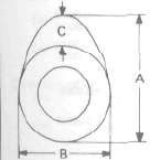 |
Cam Dimensions
Intake Exhaust |
"A" "B" "C" "A" |
35.50 mm (1.398 in) 28.00 mm (1.102 in) 7.50 mm (0.295 in) 35.50 mm (1.398 in) |
| f. | 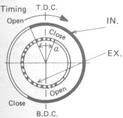 |
Valve Timing Intake: Open Close Exhaust: Open Close Over Lap |
B.T.D.C. 28° B.B.D.C. 53° 51° |
|
| 9. | 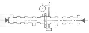 |
Camshaft Runout Limit | 0.06 mm (0.0024 in) |
|
| h. i. |
Cam Chain Type/Number of Links Cam Chain Adjustment Method |
BUSH-CHAIN/120 Automatic |
||
| 4. | Valve, Valve Seal, Valve Guide | ||||
|
a. |
Valve Clearance (Cold) IN.
|
0.11 *- 0.15 mm (0.0043 - 0.0059 in) 0.16 - 0.20 mm (0.0063 -0.0079 in) |
|||
|
b. |
Valve Dimensions |
|
|||
|
|
|
|
|||
|
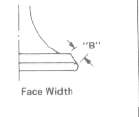
"A" Head Dia. |
33 ± 0.1 mm (1.30 ± 0.0039 in) |
||||
|
"B" Face Width |
2 3 mm (0.091 in) |
||||
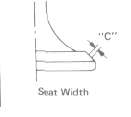
| "C" Seat Limit Width IN. EX. |
1 ± 0.1 mm (0.0394 ± 0.039 in) 1 ± 0.1 mm (0.0394 i 0 039 in) |
||||
|
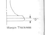
"D' Margin Thickness Limit |
0.7 mm (0.028 in) 0.7 mm (0.028 in) |
||||
|
c. |
Stem Outside Diameter |
7-0.10-0.025mm (0.2756 -0.0004-0.0010 in) |
|||
|
d |
Guide Inside Diameter |
7+0.12-0. mm (0.2756 -0.0005-0. in) |
|||
|
e. |
Stem-to guide Clearance |
0.010- 0.037 mm (0.004- 0.0015 in) |
|||
|
f. |
Stem Runout Limit |
 |
<0.03mm (0.0012 in) > |
||
|
g- |
Valve Seat Width |
1.0 mm (0.039 in) |
|||
|
6. Valve Spring |
|||||
|
a. |
Free Length |
35.9 mm (1.413 in) 39.5 mm (1.555 in) |
|||
| b. | Spring rate Inner Spring IN. EX. Outer Spring IN. EX. |
2.36 kg/mm (132 lb/in) 4.58 kg/mm (256 lb/in) |
|||
| c. | Compression Length (Valve Closed) Inner Spring IN. EX. Outer Spring IN. EX. |
31,0 mm (1.220 in) 31.0 mm (1.220 in) 34,0 mm (1.339 in) |
|||
| d. | Compression Force (Valve Closed) Inner Spring IN. EX. Outer Spring IN. EX. |
9.0 kg (20 lb) 19.1 kg (42.1 lb) |
|||
| e. | Tilt Limit, all springs: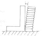 |
2.5° | |||
| f. | Direction of Winding (Top View) | Intake |
Exhaust |
||
| 7. | Piston | ||
| a. | Piston Size/ Measuring Point (A) | 63.0 mm (2.48 in)/ 7.5 mm (0.295 in) (From bottom line of piston skirt) 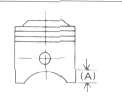 |
|
| b. | Clearance between Piston & Cylinder < Limit > |
0.03 - 0.05 mm (0.0012 -0.0020 in) <0.1 mm (0.0049 in) > |
|
| c. | 0versize 1st 2nd 3rd 4 th |
--- 63.50 mm (2.50 in) --- 64.00 mm (2.52 in) |
|
| d. | Piston Pin Hole Off-Set | 0.5 mm (0.02 in) / lnside | |
|
8. |
Piston Ring |
||
|
a. |
Sectional Sketch |
|
|
|
|
Top Ring |
B = 1.2-0.01-0.03 mm (0.47-0.0004-0.0012 in) |
|
|
|
2nd Ring |
B = 1.5-0.01-0.03 mm (0.59-0.0004-0.0012 in) |
|
|
|
Oil Ring |
B = 2.5mm (0.098 in) |
|
| b. | End Gap (Installed) Limit Top Ring 2nd Ring Oil Ring |
0.15- 0.35 mm (0.0059 - 0.0138 in) < 1.0 mm (0.039 in) > 0.15-0.35 mm (0.0059-0.0138 in) < 1.0 mm (0.039 in) > 0.3-0.9 mm (0.012 ~ 0.035 in) < 1.5 mm (0.059 in) > |
|
| c. | Side Clearance Top Ring Limit 2nd Ring Limit |
0.03-0.07 mm (0.0012- 0.0028 in) <0.15mm (0.0059 in)> 0.02-0.06 mm (0.0008-0.0024 in) <0.15mm (0.0059 in) > |
|
| d | Plating or Coating Top Ring 2nd Ring Oil Ring |
Chrome plated. Ferox coating ---- Chrome plated. Ferox coating |
|
| 9. a. b. |
Connecting Rod Oil Clearance Color Code |
0.03-0.09 mm (0.0012- 0.0035 in) 1. Blue, 2. Black, 3. Brown, 4. Green |
|
| 10. | Crankshaft | 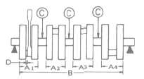 |
|
|
a. |
Crank Width "A" |
A1 = 56.15 mm (2.21 in) |
|
|
b. |
Assembly Width "B" |
341.4 ±0.6 mm (13.44± 0.024 in) |
|
|
c. |
Deflection Limit "C" |
<0.04mm (0.0016 in)> |
|
|
d. |
Big End Side Clearance "D" |
0.16-0.27 mm (0.006-0.011 in) |
|
|
e. |
Journal Oil Clearance |
0.020-0.044 mm (0.0008-0.0017 in) |
|
|
f. |
Color Code _ Corresponding Size |
1.5+0.006+0.002mm(0.0591+0.00024+0.00008in) |
|
|
Black |
1.5+0.002-0.002mm(0.0591+0.00008-0.00008in) |
||
|
Brown |
1.5-0.002-0.006mm(0.0591-0.00008-0.00024in) |
||
|
Green |
1.5-0.006-0.010mm(0.0591-0.00024-0.00039in) |
||
|
Yellow |
1.5-0.010-0.014mm(0.0591-0.00039-0.00055in) |
||
|
11. i. i |
Clutch |
3.0 ±0.1 mm (0.12 ± 0.004 in)/8 pcs. 87-91 27-32 |
|
12. |
Transmission |
<0.08mm (0.0031 in) > |
|
13. |
Shifter |
Cam drum |
|
14. |
Carburetor |
BS30/MIKUNI/4pcs. |
|
15. |
Turbocharger |
TC0306A/MITSUBISHI |
|
16. |
Lubrication System: |
|
|
a.
d. |
Oil Filter Type |
Paper filter 18+0-0.02 mm (0.709+0-0.0008 in) |
h. Lubrication Diagram
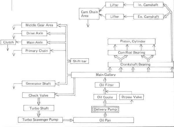

|
17. |
Middle Gear Backlash |
0.1 ~ 0.2 mm (0.0039 - 0.0079 in) |
|
18. |
Final Gear Backlash |
0.1- 0.2 mm (0.0039-0.0079 in) |
|
19. |
Crankcase Tightening Sequence |
|
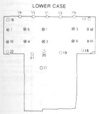
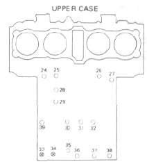
Tightening torque:
 ..... 8 mm bolt: 24 Nm (2.4 m-kg. 17.5 ft-lbl
![]() ..... 6 mm bole 12 Nm (1.2 m-kg, 8.7 ft-lbl
..... 6 mm bole 12 Nm (1.2 m-kg, 8.7 ft-lbl
|
20. Tightening Torque |
|||||||
|
Part to be tightened |
Part name |
Thread size |
Q'ty |
Tightening torque |
Remarks |
||
|
Nm |
m-kg |
1Mb |
|||||
|
ENGINE |
|||||||
|
Cylinder head |
Nut |
M10 P1 .25 |
12 |
36 |
3.6 |
25 |
Apply oil. |
|
Cylinder head cover |
Bolt |
M6 P1.0 |
20 |
1.0 |
1.0 |
7.2 |
|
|
Spark plug |
- |
|
4 |
20 |
2.0 |
14 |
|
|
Cylinder |
Nut |
M8 P1.25 |
2 |
20 |
2.0 |
14 |
Cam chain case Front & Rear |
|
Cylinder holding bolt |
Stud bolt Bolt |
M10P1.25 |
7 |
20 |
2.0 |
14 |
Apply oil |
|
Cam shaft cap |
Bolt |
M6 P1.0 |
20 |
10 |
1.0 |
7.2 |
Tighten in 3-stages. |
|
Cam sprocket |
Bolt |
M7 P1.0 |
4 |
20 |
2.0 |
14 |
|
|
Cam chain tensioner end plug |
|
M11 P1.0 |
1 |
15 |
1.5 |
11 |
|
|
Cam chain tensioner securing bolt |
Bolt |
M6 P1.0 |
2 |
10 |
1.0 |
7.2 |
|
|
Connecting rod |
Nut |
M7 P0.75 |
8 |
25 |
2.5 |
18 |
|
|
Generator (rotor) |
Bolt |
M10 PI .25 |
1 |
55 |
5.5 |
40 |
|
|
Drain plug |
Bolt |
M14 P1.5 |
1 |
43 |
4.3 |
31 |
Crankcase drain |
|
Oil filter |
Bolt |
M20 P1.5 |
1 |
15 |
1.5 |
11 |
|
|
Pump cover |
Screw |
M6 P1.0 |
|
7 |
0.7 |
5.1 |
|
|
Strainer cover |
Bolt |
M6 P1.0 |
13 |
10 |
1.0 |
7.2 |
|
|
Crankcase |
Flange Bolt |
M8 P1.25 |
12 |
24 |
2.4 |
17 |
|
|
Clutch boss |
Nut |
M20 P1.0 |
1 |
72 |
7.2 |
52 |
|
|
Clutch spring screw |
Bolt |
M6 P1.0 |
5 |
10 |
1.0 |
7.2 |
|
|
Change Pedal |
Bolt |
M6 P1.0 |
1 |
10 |
1.0 |
7.2 |
|
|
Neutral Switch |
- |
M10 P1.25 |
1 |
20 |
2.0 |
14 |
|
|
Exhaust Pipe |
Nut |
M6 P1.0 |
8 |
10 |
1.0 |
7.2 |
|
|
Oil cooler |
Joint Nut |
M22 PI.5 |
2 |
45 |
4.5 |
32 |
|
|
SHAFT DRIVE: |
|||||||
|
- Middle Gear - |
|||||||
|
Drive Shalt |
Nut |
M34 PI .5 |
1 |
110 |
11 |
80 |
Stake. |
|
Mount cover |
Screw |
M8 PI.25 |
4 |
25 |
2.5 |
18 |
Stake. |
|
Driven shaft |
Nut |
M14 Pl.5 |
1 |
120 |
12 |
85 |
Use LOCTITE: Stake |
|
Bearing cap |
Flange Bolt |
M8 P1.25 |
4 |
25 |
2.5 |
18 |
|
|
- Final Gear- |
|||||||
|
Drive Shaft |
Nut |
M14 P1.5 |
1 |
110 |
11 |
80 |
|
|
Bearing housing |
Flange Bolt |
M10 P1.25 |
2 |
23 |
2.3 |
17 |
|
|
Bearing housing |
Nut |
M8 P1.25 |
6 |
23 |
2.3 |
17 |
|
|
Oil mount screw |
Plug |
M14 P1.5 |
1 |
23 |
2.3 |
17 |
|
|
Oil drain screw |
Plug |
M14 P1.5 |
1 |
23 |
2.3 |
17 |
|
|
Bearing retainer |
|
M65 P1.5 |
1 |
110 |
11 |
80 |
Left hand screw |
- Printer-friendly version
- Log in to post comments


