LOCATION AND OUTLINE OF TURBO SYSTEM COMPONENTS
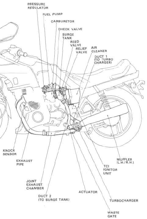
MAJOR COMPONENTS OF THE YAMAHA TURBO SYSTEM
|
EXHAUST SYSTEM |
(1) Exhaust pipe |
2) Joint exhaust |
(3) Turbocharger |
(4) Actuator |
(5) Wastegate |
(6) Muffler (L.H./R.H ) |
INTAKE SYSTEM |
(1) Air cleaner |
(21 Duct 1 (to turbocharger) |
(3) Duct 2 (to surge tank) |
(4) Surge tank |
(5) Reed valve |
(6) Relief valve |
(7) Drain valve |
FUEL SYSTEM |
(1) Electric fuel pump |
(2) Pressure regulator |
(3) Check valve |
(4) Carburetor |
LUBRICATION SYSTEM |
(1) Scavenge pump |
(2) Delivery hose (to turbocharger) |
(3) Scavenge hose (to scavenge pump) |
(4) Check valve |
(5) Oil filter |
IGNITION SYSTEM |
(1) TCI ignitor unit |
(2) Boost sensor |
(3) Knock sensor |
CONSTRUCTION OF THE TURBOCHARGER UNIT
The turbocharger unit is made up of the following components: the compressor, which produces the boost pressure by compressing air; the turbine, which converts the exhaust gas into energy to drive the compressor; the bearings, which support the rotor shaft as it rotates at high speed; and the boost pressure control unit, which is composed of the wastegate and its actuator valve.
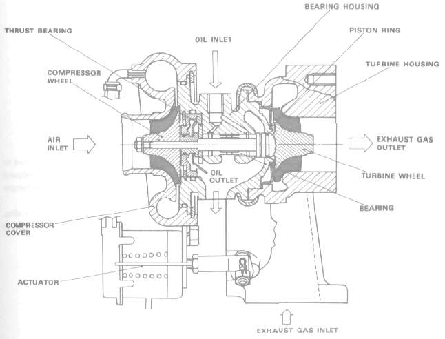
Compressor
The compressor is a rotor located within a housing of decreasing volume. As the compressor rotor turns, in excess of 100,000 rpm, it moves air by centrifugal force. Because of the design, the air being sent to the carburetors slows from its initial velocity, but because of the decreasing volume of the housing, the air pressure increase.

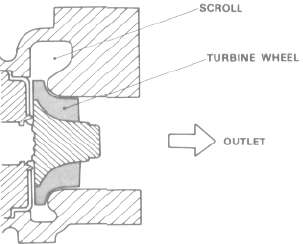
Turbine
The turbine is driven by the engine's exhaust gases. The rotating turbine, which is connected to the compressor, turns the compressor. The turbine rotor is constructed of a ultra heat-resistant alloy, which is a precision casting that can withstand high-speed operation at extreme temperatures. The turbine housing is shaped like a snail and is called a scroll casing. This design directs the exhaust gases into the turbine rotor blades. Because the turbine housing, like the turbine rotor, is subjected to high temperatures, resisting distortion and oxidation due to extremely high temperatures.
Floating bearing
Floating bearings support the turbine shaft as it turns at speeds of 100,000 to 210,000 rpm. It is the fact that these bearings "float" in a constant flow of lubricating oil that permits the turbine/compressor shaft to spin at such high rpms. These bearings are designed to turn freely between the shaft and the bearing housing. Lubricating oil surrounds the bearings, flowing freely yet absorbing the vibrations created by the turbine/compressor shaft. To ensure that the oil is not stressed any more than necessary, the bearing housing has special seals that separate the exhaust gas driving the turbine from the lubricating oil.
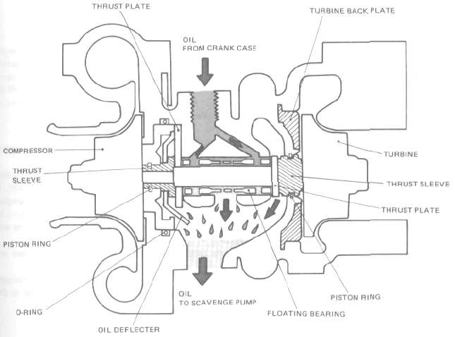
Cooling of the bearing section
During full-throttle, high speed operation the temperature of the inlet at the turbine is more than 850°C. and even the surface temperature of the turbine housing is as high as 550 to 750°C. If such heat is transferred to the center bearing housing, the bearing temperature will rise accordingly. This reduces the oil's viscosity, making it ineffective in absorbing the vibrations from the floating bearing. To guard against these high temperatures, the rear of the turbine is covered with a backing plate so that an air chamber is formed between the backing plate and the housing, thus serving as a heat insulator.
Gas seal on the turbine side
The shaft on the turbine side is provided with a ring groove into which a small-diameter ring is fitted to seal out the exhaust gas from the turbine. The ring is forced against the center bearing housing by its own tension so that it does not turn with the shaft; the shaft rotates while keeping full contact with the ring.
Oil seal on the compressor side
A ring is fitted in the groove around the thrust collar to provide a good seal.
Boost pressure control
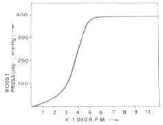
When the engine speed is low, that is, when the exhaust gas flow is not much, the boost pressure is also low. But when the engine speed increases, the turbine wheel spins faster, thus increasing the boost pressure. As engine rpms increase, so does boost pressure, further increasing power. If the boost pressure is not controlled, it will increase to the point where the engine will be damaged. To control boost pressure, a valve is used through which exhaust gas is routed to bypass the turbine. Boost pressure is thus controlled.
Wastegate valve
The wastegate is opened and closed by the actuator valve which is operated by the boost pressure. The wastegate limits the boost pressure supplied to the engine.
The boost pressure is carried from the compressor, through the rubber hose, to the actuator chamber. When the boost pressure exerted on the chamber goes beyond the preset level, it overcomes the spring force and pushes the diaphragm and linkage. This opens the wastegate valve to permit the exhaust gas to flow to the right-hand muffler. As a result, the amount of exhaust gas exerted on the turbine wheel is reduced, and thus the speed of both turbine and compressor wheels is slowed down. The result is a decrease in the boost. When the boost pressure is below 53.2 kPa (400mmHg, 15.7 inHg), all exhaust gases are channeled through the turbine vanes.
When the boost reaches 53.2 kPa (400 mmHg, 15.7 inHg), the diaphragm of the wastegate actuator causes the gate to open, and the excess exhaust gas flows through the bypass to the exhaust pipe.
Wastegate valve:
Stroke: 5 mm
Pressure: 83.4 ± 6.9 kPa (0.85 ± 0.07 kg/cm2) (12.1 ± 1.0 psi.)
- Printer-friendly version
- Log in to post comments