FAIRING REMOVAL
The fairing assembly must be removed to perform maintenance as well as major overhauling procedures. Some maintenance procedures require that only part of the fairing assembly be removed. Yamaha recommends, however, that the entire fairing assembly be removed whenever the motorcycle is serviced. This will ensure that the fairing is not damaged or unnecessarily marred.
The following table lists those fairing components that must be removed to gain access to a particular area or component:
|
|
Sections to be removed |
|
||||||||||
|
|
1 |
2 |
3 |
4 |
5 |
6 |
7 |
8 |
9 |
10 |
NOTE |
|
|
ENGINE |
A. Turbo Charger Unit |
|
|
|
o |
|
|
|
|
|
|
need not be removed, but servicing procedures will be much easier |
|
B. Valve Clearance Adjustment |
o |
o |
o |
|
o |
o |
o |
o |
o |
|
|
|
|
C. Ignition Timing |
|
|
|
o |
|
|
|
|
|
|
|
|
|
D. Air Cleaner |
o |
|
|
|
|
|
|
|
|
|
|
|
|
E. Carburetor |
o |
o |
o |
o |
|
|
|
|
|
|
|
|
|
F. Engine Oil |
o |
|
|
|
|
|
|
|
|
|
|
|
|
Q. Final Gear Oil |
|
|
|
|
|
|
|
|
|
|
|
|
|
H. Compression Pressure Measurement |
|
|
|
|
|
|
|
|
|
|
|
|
|
1. Clutch Adjustment |
|
|
|
|
|
|
|
|
|
|
|
|
|
CHASSIS |
A. Fuel Cock |
o |
o |
o* |
o* |
|
|
|
|
|
|
*Loosen the securing bolts |
|
B. Front and Rear Brake |
|
|
|
|
|
|
|
|
|
|
|
|
|
C. Tubeless Tires and Aluminium Wheels |
|
|
|
|
|
|
|
|
|
|
|
|
|
D. Front Fork Oil Change |
|
|
|
|
|
|
|
|
|
|
|
|
|
E. Rear Shock Absorber |
|
|
|
|
|
|
|
|
|
o |
|
|
|
F. Steering Head Adjustment |
|
|
|
|
|
|
|
|
|
o |
|
|
|
G. Cable Inspection and Lubrication |
o |
|
o |
|
|
|
|
|
|
|
Clutch cable inspection |
|
|
H. Throttle Cable and Grip Lubrication |
o |
|
o |
|
|
|
|
|
|
|
|
|
|
1. Rear Arm Pivot Bearings |
|
|
|
|
|
|
|
|
|
|
|
|
|
J. Brake and Change Pedals/Brake and Clutch Lever |
|
|
|
|
|
|
|
|
|
|
|
|
|
K. Center and Side Stand Pivots |
|
|
|
|
|
|
|
|
|
|
|
|
|
ELECTRICAL |
A. Battery |
o |
|
o |
|
|
|
|
|
|
|
|
|
B. Spark Plug |
|
|
|
|
|
|
|
|
|
|
|
|
|
C. Headlight |
|
|
|
|
|
|
|
|
o |
|
|
|
|
D. Fuse |
o |
|
|
|
|
|
|
|
|
|
|
|
1 SEAT

2 FUEL TANK

3 SIDE PANEL

4 LOWER PANEL

5 UPPER PANEL (Right)

6 UPPER PANEL (Left)

7 WINDSCREEN

8 HEADLIGHT NACELLE

9 FRONT FLASHER LIGHTS


10 REAR MOLDING

Fairing Removal
1. Remove the seat.
To open the seat lock, insert the key in the lock. Then, turn it clockwise and pull the lever backward.
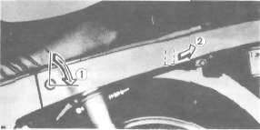
1. Open 2. Pull
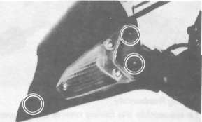
2. Remove the lower panel securing bolts (3X2) and remove the lower panel as one piece.


3. Remove the front securing bolts (2) and the side securing bolts (2).

4. Remove the side panels as one piece. Grasp the panels on either side where the panels are joined to the frame. Pull the male connectors out; then pull the rear of the panels up.

5. Remove the headlight nacelle.

6. Remove the left and right front flashers (3X2); disconnect the lead couplers.
7. Remove the windscreen with the rear view mirrors (2X2).

8. Remove the two clips.

9. Remove the left and right upper panels.

10. Remove the securing bolts (4) and remove the rear molding while prying the ends apart.

Fairing Reassembly
To reassemble the fairing reverse the removal procedure.
Fuel Tank Removal
1. Remove the fuel tank securing bolt.

2. Disconnect the overflow pipe and emergency engine stop switch lead connecter.
3. Disconnect the fuel lines.
4. Remove the fuel tank.
Oil Cooler Removal
1. Place an open container under the engine.
2. Remove the oil cleaner cap bolt.

3. Remove the spacer securing bolt.

4. Loosen the oil hose fitting nuts (2); then remove the oil cooler holding bolts (2) and the clamp bolt.
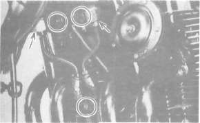
5. Remove the oil cooler assembly, pulling down and then away from the motorcycle.

Oil Cooler Installation
1. Install a new "O-ring" and install the oil cooler spacer to the crankcase. Make sure the "O-ring" is positioned properly.

1.O-ring
2. Tighten the spacer securing bolt.
Tightening torque:
50 Nm (5.0m.kg, 36 ft-lb)
3. Install the oil filter element into the filter cover and install a new "O-ring". Make sure the "O-ring" is positioned properly.

1. O-ring
4. Tighten the oil cleaner cap bolt.
Tightening torque:
15 Nm (1.5 mkg, 11 ft-lb)
5. Tighten the oil cooler holding bolts (2).
Tightening torque:
10 Nm (1.0 m-kg, 7.2 ft-lb)
6. Tighten the clamp bolt.
Tightening torque: 10 Nm (1.0 m-kg, 7.2 ft-lb)
7. Tighten the oil hose fitting nuts (2).
Tightening torque: 45 Nm (4.5 m-kg, 32 ft-lb)
- Printer-friendly version
- Log in to post comments