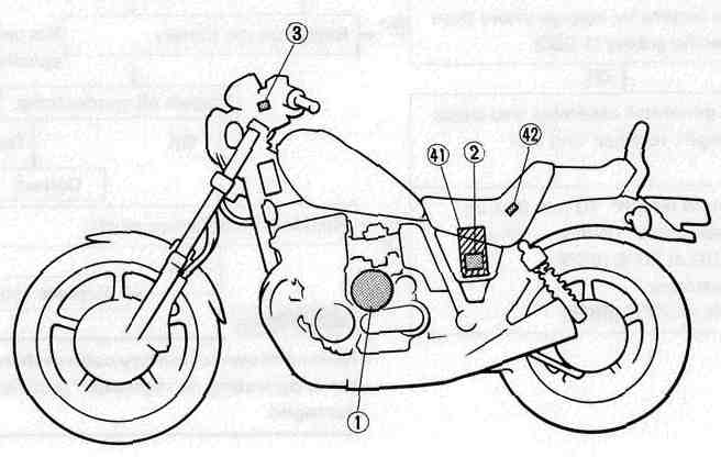
CHARGING SYSTEM

1 A.C. Generator 2 Rectifier/Regulation 3 Main switch
41 Battery 42 Fuse "MAIN" (30A)

CHARGING VOLTAGE INSPECTION
1. Remove seat
2. Connect Pocket Tester leads (to each battery terminal)
3. Start the engine.
4. Measure the charging voltage. Rev engine to approximately 3,000 r/min or more.
Charging Voltage: 14.2 ~ 14.8 V
TROUBLESHOOTING
| Check voltage. | ◄ ◄ ◄ ◄ | ◄ | |
| Not within specification ▼ | ▲ | ||
|
Inspect all connections |
Defective ► | Correct.► | ▲ |
| OK ▼ | |||
| Measure the battery for voltage and specific gravity. Battery voltage: More than 12V Specific gravity: 1.280 |
Less than specification: ► | Recharge the battery. | |
|
OK ▼ |
|||
|
Remove the generator assembly and check the brush length, rectifier, and coil resistance. Minimum brush length: 10 mm (0.39 in) |
Less than specification: ► | Replace the defective part(s). | |
|
OK ▼ |
|||
| Replace rectifier/regulator. | |||
BATTERY
NOTE:
Replace the battery if:
•Battery voltage will not rise to a specific value or bubbles fail to rise even after many hours of charging.
•Sulfation of one or more cells occurs, as indicated by the plates turning white, or an accumulation of material exists in the bottom of the cell.
•Specific gravity readings after a long, slow charge indicate one cell to be lower than the rest.
•Warpage or buckling of plates or insulators is evident.
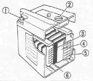
1 Terminal
2 Cap
3 Insulator
4 Separation plate
5 Negative electrode
6 Positive electrode
1. Inspect the battery terminals and battery couplers. Clean off any corrosion. Tighten as required.
2. Measure the specific gravity of battery fluid. Remove and recharge battery if less than 1.280
CAUTION:
To insure maximum battery performance be sure to:
• Charge a new battery before use.
• Maintain proper electrolyte level.
• Charge at proper current; 1.4 amps/10 hrs. or until the specific gravity reaches 1.280 at 20°C(68°F).
Failure to observe these points will result in a shortened battery life.

WARNING:
Battery electrolyte is dangerous; it contains sulfuric acid and therefore is poisonous and highly caustic.
Always follow these preventive measures:
•Avoid bodily contact with electrolyte as it can cause severe burns or permanent eye injury.
•Wear protective eye gear when handling or working near batteries. Antidote (EXTERNAL):
•SKIN - Flush with water.
•EYES — Flush with water for 15 minutes and get immediate medical attention. • Drink large quantities of water or milk and follow with milk of magnesia, beaten egg, or vegetable oil. Get immediate medical attention.
Batteries also generate explosive hydrogen gas, therefore you should always follow these preventive measures:
• Charge batteries in a well-ventilated area.
• Keep batteries away from fire, sparks, or open flames (e.g., welding equipment, lighted cigarettes, etc.)
• DO NOT SMOKE when charging or handling batteries. KEEP BATTERIES AND ELECTROLYTE OUT OF REACH OF CHILDREN.
Battery Service Life
The service life of a battery is usually two to three years. Battery life may be shortened by poor maintenance.
Preparation steps:
• Keep battery topped off with distilled water.
• Keep battery charged.
• Do not overcharge battery.
• Do not allow battery to freeze.
• Do not fill with tap water or sulfuric acid containing impurities.
• Do not charge new battery using improper voltage or current.
Battery Storage
The battery should be stored if the motorcycles is not to be used for a long period.
1. Remove the battery.
Battery storage and maintenance tips:
• Recharge the battery periodically.
• Store the battery in a cool, dry place.
• Recharge the battery before reinstalling.
|
Battery |
YB14L |
|
Electrolyte |
Specific gravity: 1.280 |
|
Initial charging rate |
1.4 amp for 10 hours (new battery) |
|
Recharging rate |
10 hours (or until specific gravity reaches 1.280) |
|
Refill fluid |
Distilled water (to maximum level line) |
|
Refill period |
Check once per month (or more often as required) |
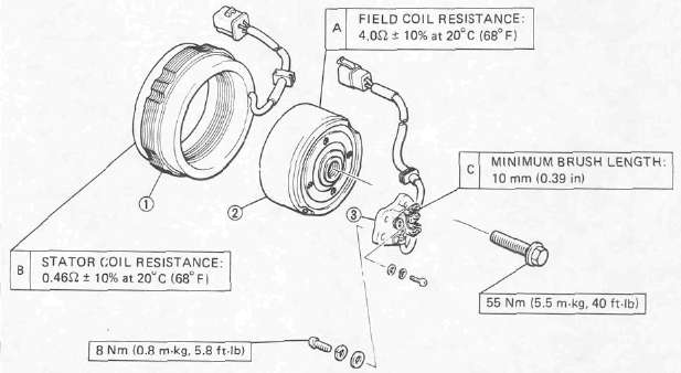
1 Field coil
2 Stator
3 Brush
GENERATOR ASSEMBLY

1. Remove:
• Left side cover
• Panel
2. Measure the stator coil resistance
Stator Coil Resistance: 0.46Ω ± 10% at 20°C (68°F) (W-W)

3. Remove the A.C.G. cover
4. Measure the field coil resistance
Field Coil Resistance: 4.0Ω ±10% at 20°C (68°F)
5. Inspect the brush contact areas. Clean with 600 grit sandpaper if dirty.
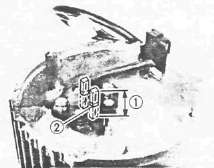
6. Measure each brush length 1. Replace if shorter than minimum.
Minimum Brush Length: 10 mm (0.39 in)
2 Wear indicator
7. Inspect the brush springs Compare with new spring.
RECTIFIER/REGULATOR

1. Remove:
• Left side cover
• Panel
2. Check Rectifier/Regulator 1 diodes (Refer to the following table.)
Defective element — Replace rectifier.

1 White
2 White
3 White
4 Red
5 Ground
6 Brown
A Regulator
B Rectifier
|
Checking |
Pocket tester |
Good |
|
|
(+) |
(-) |
||
|
D1 |
4 |
1 |
O |
|
1 |
4 |
X |
|
|
D2 |
4 |
2 |
O |
|
2 |
4 |
X |
|
|
D3 |
4 |
3 |
O |
|
3 |
4 |
X |
|
|
D4 |
1 |
5 |
O |
|
5 |
1 |
X |
|
|
D5 |
2 |
5 |
O |
|
5 |
2 |
x |
|
|
D6 |
3 |
5 |
O |
|
5 |
3 |
x |
|
O: Continuity X: Discontinuity (∞ )
CAUTION:
Do not overcharge rectifier or damage may result.
Avoid:
• A short circuit
• Inverting + and - battery leads
• Direct connection of rectifier to battery
NOTE:
The results "O" or "x" should be reversed according to the pocket tester polarity.
- Printer-friendly version
- Log in to post comments