I. Crankshaft
1. Crankshaft run-out
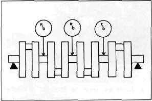
Support the crankshaft at both ends on V-blocks. Measure the amount of crankshaft run-out on the main bearing journals with a dial gauge while rotating crankshaft.
Run-out limit: 0.030 mm (0.0012 in)
If run-out exceeds limit, replace crankshaft.

2. Inspection of bearings
Check the bearings. If the inner or outer surface is burned, flaked, rough, scratched or worn, the bearings should be replaced.
3. Measuring main bearing oil clearance
a. Clean all crankshaft and crankcase journal surfaces.
b. Place upper crankcase half upside-down on a bench. Install bearing inserts into top crankcase.
c. Install crankshaft into upper crankcase.
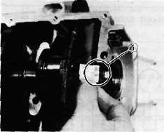
d. Place Plastigage on crankshaft journal surface to be inspected.
NOTE:
Do not move crankshaft until clearance check has been completed.
e. Install bearings into bottom crankcase. Carefully, place lower crankcase onto upper crankcase.
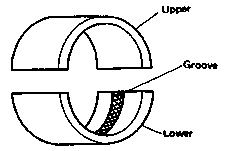
The crankshaft main bearing which has no groove on the bearing surface should be installed in the upper crankcase.

f. Install crankcase holding bolts 1 through 10. Tighten to full torque in torque sequence cast on crankcase.
Crankcase torque (8 mm bolt): 2.4 m-kg (17 ft-lb)

g. Remove bolts in reverse assembly order (10,9,8... etc.)
h. Carefully remove lower crankcase. Measure width of Plastigage on crankshaft journals to determine clearance.
Main bearing oil clearance: 0.020 - 0.044 mm (0.0008-0.0017 in)

1. Plastigage
4. Crankshaft main bearing selection a. Numbers used to indicate crankshaft journal sizes are stamped on the L.H. crank web. The first five (5) are main bearing journal numbers, starting with the left journal. The four (4) rod bearing journal numbers follow in the same sequence.

For greater clarity:

The upper crankcase half is numbered 4, 5, or 6 as shown.

1. Main bearing numbers
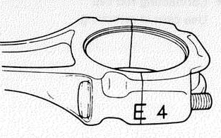
b. The connecting rods are numbered 3 or 4. The numbers for rods are stamped with ink on the rod itself.

1. Connecting rod size number
c. The proper bearing selection is made by subtracting the crankshaft journal number from the crankcase or rod size number. Use the color code to choose the proper bearing.
EXAMPLE:
Rod No. (Minus) Journal No. = Bearing No. 5-2 = 3 No. 3 bearing is Brown. Use Brown bearing inserts.
|
BEARING COLOR CODE |
|
|
No. 1 |
Blue |
|
No. 2 |
Black |
|
No. 3 |
Brown |
|
No. 4 |
Green |
|
*No. 5 |
Yello |
#For crankshaft main bearing only.
d. When assembling, apply a liberal coat of motor oil to all bearing surfaces.
NOTE:
When applying final torque to the rod caps, observe the following procedures:
e. Be sure the letter on both components align to form a perfect character:

f. Apply molybdenum disulfide grease to connecting rod bolt threads. Apply torque evenly to both ends of the cap. While tightening, if a torque of 2.0 m-kg (14.5 ft-lb) or more is reached, DO NOT STOP tightening until final torque is reached. If tightening is interrupted between 2.0 m-kg and 2.5 m-kg, loosen the nut to less than 2.0 m-kg and start again. Tighten to full torque specification (25 m-kg, 18 ft-lb) without pausing.
- Printer-friendly version
- Log in to post comments
