11. Pistons and cylinder
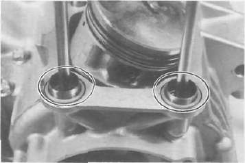
a. Install the pistons on the rods. The arrow on the piston must point to the front of the engine.
NOTE: Before installing the piston pin clips, cover the crankcase with a clean rag so you will not accidentally drop the circlip into the crank-case. Always install new piston pin circlips.

b. Install the rear chain guide on its pivot. Tighten the holding bolt until it stops and then loosen 1/4 turn and then tighten the lock nut

1. Holding bolt 2. Rear cran guide
c. Install the new cylinder base gasket and dowel pins. Install the new "O-rings" to the right side dowel pins.
d. Set the crankshaft so that the all pistons are equal height and align the piston rings as shown.
CAUTION: Make sure the ends of the oil ring expanders are not overlapped.
NOTE: Manufacture's marks or numbers stamped on the rings are en the top side of the rings. Coat the pistons and rings well with oil.

e. Install the piston ring compressors (special tool) and piston bases (special tool). Four piston bases are required.

1. Piston bases 2. Piston ring compressors
f. Tie the cam chain with a piece of mechanic's wire and feed it through the chain opening. Carefully lower the cylinder onto the pistons. Remove the ring compressors and piston bases and repeat this procedure for pistons 1 and 4.

g. Install the cylinder securing nut (front side) and tighten it to the specification.
Tightening torque:
20 Nm (2.0 mkg, 14 ft lb)

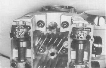
h. Set the dial gauge on the No. 1 piston head center as shown to find the No. 1 piston top dead center and check whether the "T" mark on the timing plate and stationary pointer are aligned or not. If not, loosen the pointer securing screw and adjust.

CYLINDER HEAD


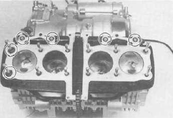
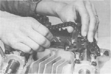
12. Cylinder head and cam shafts a. Install the new cylinder head gasket. Install the dowel pins and "O-rings". Locate the cam chain cavity cylinder seal with the tabs down.
b. Install the cylinder head onto the cylinder. Pull the cam chain through the cylinder head as it is installed. Tie the cam chain so that it does not fall into the crankcase.
c. Place the upper cylinder head nuts and washers in place. Follow the illustration for the proper tightening sequence. Torque all nuts in two stages and final torque the upper nuts to the specification.
Tightening torque:
32 Nm (3.2 mkg, 23 ft lb)
NOTE: Don't forget the lower nuts on the front and rear of the cylinder head. Torque to the specification.
Tightening torque: 20 Nm (2.0 mkg, 14ft-lb)
NOTE: Tighten the nuts in two stages, 1/2 torque value and then full torque value. Also lubricate the bolt threads with the engine oil to achieve proper torque values.
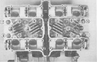
a. Copper washers
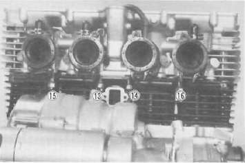

d. Install the front cam chain guide being certain that it is in its holder down below.
e. Rotate the crankshaft counterclockwise direction until the crankcase pointer and "T" mark on the timing plate are aligned.


f. With the cylinders No. 1 and 4 at the top dead center, slip the cam chain over the sprocket.

cj. Lubricate all cam caps and cam bearings surfaces liberally with oil.
h. Place the cam caps in their proper positions. Install the bolts only finger tight.
CAUTION: The cam caps must be tightened evenly or damage to the cylinder head, cam caps and cam will result. The spaces between the caps and cylinder head should be equal.

i. Torque the cam cap bolts in two stages and final torque to the specification.
Tightening torque:
10 Nm (1.0 m-kg, 7.2 ft-lb)
CAM CHAIN

13. Cam chain, cam sprockets and chain tensioner a. Rotate each cam shaft until the dot on the cam is aligned with the hole on the right cam cap.
CAUTION: Use extreme caution when rotating the cams. Two possible dangers exist. First, the wrench may contact the head and fracture it. Or second, a valve may become bent if the cam is turned the wrong way.
b. Carefully lift the cam chain from the exhaust cam sprocket and pull upward to remove any slack in the chain between the crankshaft and the exhaust cam sprocket. With all slack removed, place the chain back on the cam sprocket.

c. Grip each sprocket simultaneously and place them on the camshaft shoulders while continuing to keep tension on the chain from the crankshaft to the exhaust sprocket
CAUTION: Use only the special hardened shouldered bolts to install the cam chain sprockets to the cams.
Make sure the rollers of the cam chain are centered on both chain guides.
d. Rotate the sprockets slightly to align the bolt holes and insert one special bolt in each sprocket.
NOTE: Tighten only finger tight at this time.
e. Install the center chain guide.
f. Rotate the crankshaft counterclockwise and align the "C" mark on the timing plate with the timing pointer.

g. Remove the end plug and spring from the tensioner assembly.
h. Unlock the oneway cam by pushing it with your finger and push the tensioner rod into the tensioner body until it stops.

i. Install the tensioner to the cylinder and torque the bolts to the specification.
Tightening torque:
10 Nm (1.0 m-kg, 7.2 ft-lb)
j. Reinstall the spring and end plug with the gasket. Torque the end plug to the specification.
Tightening torque:
15 Nm (1.5 m-kg, 11 ft-lb)

k. Rotate the crankshaft more than one full revolution and align the "T" mark on the timing plate with the timing pointer. With the crankshaft at the "T" mark, the dots on the cams should be aligned with the raised holes on the right cam caps. If they are not aligned, disassemble the sprockets and chain tensioner and repeat above procedures.
I. Rotate the crankshaft and install the two remaining shoulder bolts into the cam sprockets. Torque all four sprocket holding bolts to the specification.
CAUTION: Be sure to attain the specified torque value to avoid the possibility of these bolts coming loose and causing serious damage to the engine.
Tightening torque:
20 Nm (2.0 m-kg, 14 ft-lb)

m. Adjust all valves as described in the "PERIODIC INSPECTIONS AND ADJUSTMENTS".
n. Install the cylinder head cover with a new gasket.
o. Install the left and right crankcase covers. The left crankcase cover (pickup coil cover) is required a gasket.
Middle gear servicing
1. Disassembly
Refer to page 3-13 for disassembly.
2. Inspection
Refer to page 3-29 for inspection.
3. Gear lash check
NOTE: The middle gear lash can be checked only when the gears are installed in the crankcase.
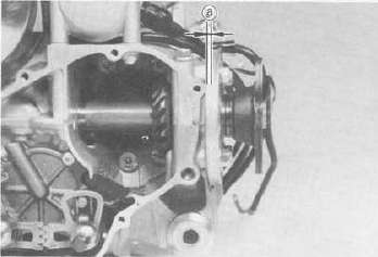
a. Install the middle drive pinion holder (special tool) on the crankcase to hold the drive gear stationary during the lash measurement.
NOTE: Before installing the tool, loosen the holder bolt all the way out and after installation tighten this bolt as tight as necessary (finger tight is generally sufficient).

1. Middle drive pinion holder
b. Set the dial gauge to the middle drive flange as shown and gently rotate the drive flange back and forth. Note the lash measurement on the dial gauge.
Middle gear lash: 0.1 ~~ 0.2 mm (0.004 - 0.008 in)

a Middle gear lash
c. Check this engagement at 4 positions. Rotate the drive flange 90° each time and repeat the gear lash check.
NOTE: If the gear lash exceeds the specified limit and adjustment is necessary, the engine or swing arm should be removed from the motorcycle.
4. Gear lash adjustment a. Install the driven gear housing assembly into the crankcase leaving about a 2 mm (0.08 in) gap between the housing and crankcase and install the two bolts to the bearing housing 180° opposite to each other.
a. 2 mm (0.080 in)
b. Install the middle drive shaft holder and dial gauge (refer to "Middle gear lash check").
c. Slowly tighten the bolts alternately until the dial gauge lash measurement reaches 0.2 mm (0.008 in).
- Printer-friendly version
- Log in to post comments