Fuel sender unit
1. Inspection
a. Remove the sender unit from the fuel tank.
b. Use a pocket tester (with ohm x 10 scale) for this check. Connect the pocket tester leads across the green lead and the black lead of the sender unit. The meter should show the following resistance at the specified fuel level. If not replace the sender unit.
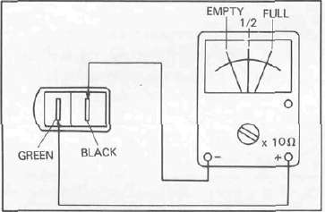
|
Fuel sender resistance |
|
| Full | 2—12Ω |
| 1/2 | 40Ω |
| Empty | 87.5 — 102.5 Ω |
Oil level switch
1. Inspection
a. Remove the oil level switch from the engine.
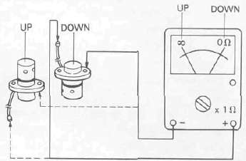
b. Use a pocket tester (with ohm x 1 scale) for this check.
Connect the pocket tester lead as shown.
When the oil level switch stands up right the tester should read infinity. When the oil level switch stands up side down, the tester should read 0 ohms.
Tachometer
1. Description
This model has been equipped with an electric tachometer. This tachometer receives its impulses from one of the stator leads of the alternator.
2. Inspection
a. If the tachometer should become inoperative, the following troubleshooting steps will be useful.
1) Remove the headlight rim.
2) Turn the ignition switch to the "ON" position.
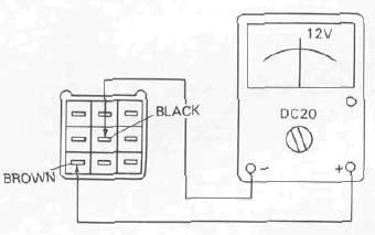
3) Inside the headlight shell disconnect the tachometer leads from the main harness.
Use a pocket tester to check and set the meter selector to the "DC 20" position.
| Connect tester leads between brown and black leads from main harness.
Meter should show 12 volts D. C. |
Less than 12 volts or no voltage ► |
Weak connection or open circuit between fuse and main harness |
| YES ▼ |
||
| Replace tachometer assembly | ||
Digital clock
1. Inspection
If the digital clock should become inoperative, the following troubleshooting steps will be useful.
a. Remove the headlight rim.
b. Turn the ignition switch to the "ON" position.
c. Inside the headlight shell disconnect the digital clock leads from the main harness. Use a pocket tester to check and set the meter selector to the "DC 20" position.
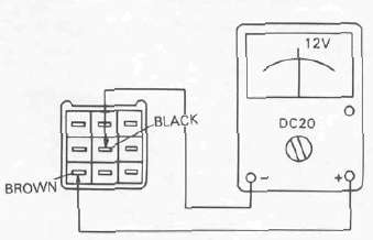
| Connect tester leads between brown and black leads from main harness.
Meter should show 12 volts D. C |
Less than 12 volts or no voltage ► |
Weak connection or open circuit between fuse and main harness |
| YES ▼ |
||
| Replace digital clock assembly | ||
2. Adjustment
This digital clock always show the time regardless of the main switch position.
To set the time:
Turn ignition "ON"
Set hour by pushing or holding the "H" switch.
Set minutes by pushing or holding the "M" switch.
NOTE: If setting the clock after the power source has been interupted (eg: disconnected battery, blown fuse) It may be necessary to first hold the "H" switch for 10 seconds; before setting the correct time.
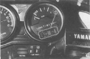
1. Digital clock
Switches
Switches may be checked for continuity with a pocket tester on the "ohm x 1" position.
1. Main switch
|
Switch Position |
Wire Color | |||
| R | Br | L | L/R | |
| OFF | ||||
| ON |  |
 |
||
| P (parking) |  |
|||
2. "ENGINE STOP" switch
| Switch Position | Wire Color | |
| R/W | R/W | |
| RUN |  |
|
| OFF | ||
3. "LIGHTS" switch (right handlebar)
| SwitchPosition | Wire Color | ||
| R/Y | L | L/B | |
| ON |  |
||
| PO |  |
||
| OFF | |||
4. Starter switch (right handlebar)
| Button Position | Wire Color | |
| L/W | B | |
| OFF | ||
| ON |  |
|
5. "LIGHTS" (Dimmer) switch
| Switch Position | Wire Color | ||
| Y | L B | G | |
| HI |  |
||
| LO |  |
||
6. "TURN" switch (left handlebar)
| Switch Position | Wire Color | ||||
| Dg | Br/W | Ch | Y/R | B | |
| R |  |
 |
|||
| R —N |  |
||||
| N — Push | |||||
| L —N |  |
||||
| L |  |
 |
|||
7. "HORN" switch (left handlebar)
| Switch Position | Wire Color | |
| P | B | |
| PUSH |  |
|
| OFF | ||
8. Passing light switch (left handlebar)
| Button Position | Wire Color | |
| Y | R/Y | |
| OFF | ||
| PUSH |  |
|
- Printer-friendly version
- Log in to post comments
