Valve, valve guide, and valve seat
1. Check the valve face and the stem end for wear. If the valve face and/or the stem end are pitted or worn, regrind the valve with a valve refacer. Replace the valve if any dimension exceeds the specifications in the illustration.

Intake/Exhaust valve
Minimum thickness (Service limit) 0.7 mm (0.028
Minimum length (Service limit) 4.0 mm (0.157 in)
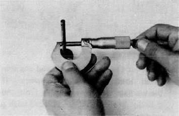
2. Valve stem wear must be measured and then combined with valve guide measurements to guide clearance. This clearance must be within tolerances. If it exceeds the maximum limit, then replace either or both valve and guide, as necessary.
|
Valve Stem Clearance |
Maximum |
|
|
Intake |
0.010 ~ 0.037 mm (0.004 -0.0015 in) |
0.10 mm (0.004 in} |
|
Exhaust |
0.025 ~ 0.052 mm (0.0010-0.0020 in) |
0.12 mm (0.005 in) |


3. Valve stem end
Inspect the end of the valve stem. If the end appears to be "mushroomed" or has a larger diameter than the rest of the stem, the valve, valve guide, and oil seal should be replaced.
4. Turn valve on "V" blocks and measure the amount of stem runout with a dial guage. If it exceeds the maximum limit, replace the valve.
Maximum valve stem runout: 0.03 mm (0.0012 in)

5. Valve guide and valve oil seal replacement If oil leaks into the cylinder through a valve due to a worn valve guide, or if a valve is replaced, the valve guide should also be replaced.
NOTE:
The valve oil seal should be replaced whenever a valve is removed or replaced.
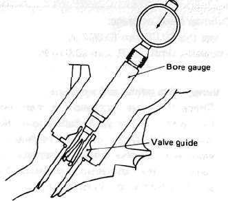
a. Measure valve guide inside diameter with a small bore gauge. If it exceeds the limit, replace with an oversize valve guide.
Guide diameter (I.D.): Limit: 6.10 mm (0.240 in!
b. To ease guide removal and reinstallation, and to maintain the correct interference fit, heat the head to 100°C (212°F). Use an oven to avoid any possibility of head warpage due to uneven heating.
c. Use the appropriate shouldered punch (special tool) to drive the old guide out and drive the new guide in,
NOTE:
When a valve guide is replaced, the O-ring should also be replaced.

1. Valve guide installer
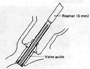
d. After installing the valve guide, use the 6 mm reamer (special tool) to obtain the proper valve guide to valve stem clearance.

e. After installing the valve guide in the cylinder head, the valve seat must be recut. The valve should be lapped to the new seat.
6. Grinding the Valve Seat
a. The valve seat is subject to severe wear. Whenever the valve is replaced or the
valve face is re-surfaced (see caution) The valve seat should be re-surfaced at a 45° angle. If a new vlave guide has been installed the valve seat must be recut to guarantee complete sealing between the valve face and seat.

CAUTION:
If the valve seat is obviously pitted or worn, it should be cleaned with a valve seat cutter. Use the 45° cutter, and when twisting the cutter, keep an even downward pressure to prevent chatter marks.
If cutting section "A" of the valve seat, use 30° cutter. If cutting section "B", use the 45° cutter. If cutting section "C" use 60° cutter. b. Measure valve seat width. Apply mechanic's bluing dye (such as Dykem) to the valve face and valve seat, apply a very small amount of fine grinding compound around the surface of the valve face insert the valve into position, and spin the valve quickly back and forth. Lift the valve, clean off all grinding compound, and check valve seat width. The valve seat and valve face will have removed bluing wherever they contacted each other. Measure the seat width with vernier calipers. It should measure approximately 1.1 mm (0.0433 in). Also, the seat should be uniform in contact area. If valve seat width varies, or if pits still exist, further cutting will be necessary. Remove just enough material to achieve a satisfactory seat.
|
Standard Width |
Wear Limit |
|
|
Seat width |
1.0* 0.1 mm (0.0394 ±0.0039 in) |
2.0 mm (0.080 in) |

1. Valve guide remover

a. Seat width
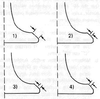
c. If the valve seat is uniform around the perimeter of the valve face, but is too wide or not centered on the valve face, it must be altered. Use either the 30°, 45° or 60° cutters to correct the improper seat location in the manner described

1) If the valve face shows that the valve seat is centered on the valve face, but too wide, then lightly use both the 30° and the 60° cutters to reduce the seat width to 1.1 mm (0.0433 in).

1. Valve seat cutter
2) If the seat shows to be in the middle of the valve face, but too narrow, use the 45° cutter until the width equals 1.1 mm (0.0433 in).
3) If the seat istoo narrow and right up near the valve margin, then first use the 30° cutter and then the 45° cutter to get the correct seat width.
4) If the seat is too narrow and down near the bottom edge of the valve face, then first use the 60° cutter and then the 45° cutter.
7. Lapping the valve/valve seat assembly
a. The valve/valve seat assembly should be lapped if neither the seat nor the valve face are severely worn.
b. Apply a small amount of coarse lapping compound to valve face. Insert the valve into the head. Rotate the valve until the valve and valve seat are evenly polished. Clean off the coarse compound, then follow the same procedure with fine compound.
Continue lapping until the valve face shows a complete and smooth surface all the way around. Clean off the compound material. Apply bluing dye to the valve face and seat and rotate the valve face for full seat contact which is indicated by a grey surface all around the valve face where the bluing has been rubbed awav.

Valve leakage check
After all work has been performed on the valve and valve seat, and all head parts have been assembled, check for proper valve/valve seat sealing by pouring solvent into each of the intake ports, then the exhaust ports. There should be no leakage past the seat. If fluid leaks, disassemble and continue to lap with fine lapping compound. Clean all parts thoroughly, reassemble and check again with solvent. Repeat this procedure as often as necessary to obtain a satisfactory seal.
- Printer-friendly version
- Log in to post comments
