Maintenance Specifications -- Electrical
C. Electrical
|
1. |
Voltage |
12V |
||
|
2. |
||||
- Read more about Maintenance Specifications -- Electrical
- Log in to post comments
C. Electrical
|
1. |
Voltage |
12V |
||
|
2. |
||||
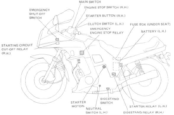
EMERGENCY SHUT-OFF SWITCH
The emergency shutoff switch is a mechanical switch and mounted behind the headlight. This switch will shut off the ignition system if for any reason the motorcycle reaches a lean angle of 60 degrees or more from vertical.
Removal
1. Remove the required fairing.
2. Disconnect the lead wires from the wire harness and pull out the switch assembly from its rubber mounting harness.
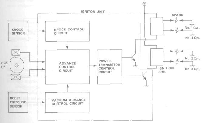
This motorcycle is equipped with the conventional transistor advance system as well as a semi conductor controlled boost sensor and a knock sensor. These combine to produce the optimum ignition timing according to engine conditions (i.e., engine speed, load, knocking, etc.).
Ignition system block diagram
VACUUM ADVANCE CONTROL SYSTEM
LUBRICATION SYSTEM
The turbo unit is pressure-lubricated from the main engine oil gallery. A check valve is installed on the outlet o' the engine main oil gallery to stop oil flow to the turbo unit when the engine is not running. A scavenging pump rotor is equipped behind the original oil pump rotor to retrieve the oil from the turbo unit, ensuring a constant flow of oil.
Check valve opening pressure: 24.5 kPa (0.25 kg/cm , 3.56 psi)
FUEL PUMP
The fuel pump is operated by a DC motor that is directly coupled to the pump. Fuel from the fuel cock is drawn into the pump, flows around the motor to the outlet at the opposite end of the housing, and then is fed through the check valve.
FAIRING REMOVAL
The fairing assembly must be removed to perform maintenance as well as major overhauling procedures. Some maintenance procedures require that only part of the fairing assembly be removed. Yamaha recommends, however, that the entire fairing assembly be removed whenever the motorcycle is serviced. This will ensure that the fairing is not damaged or unnecessarily marred.

Above circuit diagram shows only ignition circuit in wiring diagram.

B. Description

Above circuit diagram shows starter circuit in wiring diagram.
B. Starter Motor
1. Removal (see CHAPTER 3. "ENGINE DISASSEMBLY")
2. Inspection and repair