Chapter 2, PERIODIC MAINTENANCE
CHAPTER 2. PERIODIC INSPECTIONS AND ADJUSTMENTS
INTRODUCTION
- Read more about Chapter 2, PERIODIC MAINTENANCE
- Log in to post comments
CHAPTER 2. PERIODIC INSPECTIONS AND ADJUSTMENTS
INTRODUCTION
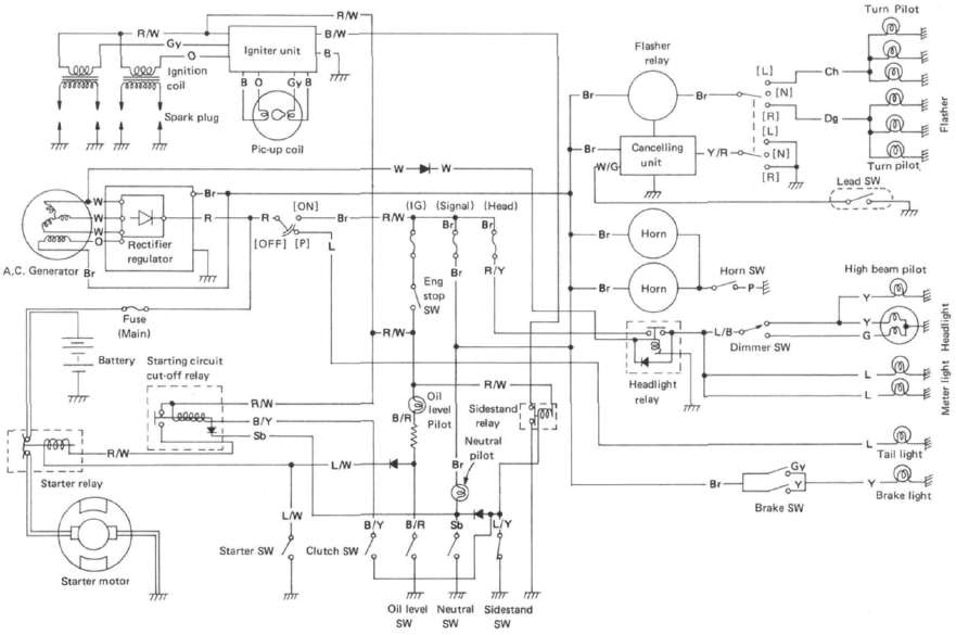
XJ650RJ CIRCUIT DIAGRAM
ELECTRIC STARTING SYSTEM
STARTING CIRCUIT OPERATION
The starting circuit on this model consists of the starter motor, starter relay, and the starting-circuit cut-off relay. If the engine stop switch and the main switch are both on, the starter motor can operate only if:
a. The transmission is in neutral (the neutral switch is on).
or if
HTML clipboard
IGNITION SYSTEM A. Circuit Diagram

Above circuit diagram shows only ignition circuit in wiring diagram.

B. Description
ELECTRICAL COMPONENTS


SPECIFICATIONS
General Specifications
|
|
XJ650G |
|
Basic color Dimensions: Overall length |
ELECTRICAL
A. Battery
1. The fluid level should be between the upper and lower level marks. Use only distilled water if refilling is necessary.
CAUTION:
Normal tap water contains minerals which are harmful to a battery; therefore, refill only with distilled water.
CHARGING SYSTEM
A. Circuit Diagram
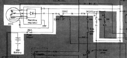
Above circuit diagram shows charging circuit in wiring diagram.
B. A.C. Generator
1. Checking method.
a. Connect D.C. voltmeter to the battery terminals.
HTML clipboard
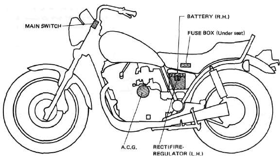
CABLE ROUTING


LIGHTING SYSTEM
A. Circuit Diagram

Above circuit diagram shows only lighting circuit in wiring diagram.

B. Lighting Tests and Checks