Engine Maintenance
ENGINE
A. Valve Clearance Adjustment
- Read more about Engine Maintenance
- Log in to post comments
ENGINE
A. Valve Clearance Adjustment
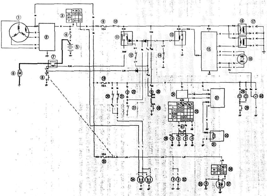
3. Main switch
4. Main fuse
5. Battery
32 Meter light (3.4w x 2)
33. Headlight fuse (10A)
34 Brake/tail light (27/8W)
35. High beam indicator (3.4W)
36. Headlight dimmer switch
37. Headlight (60/55W)
SHAFT DRIVE
Refer to "CHAPTER 3". for the middle gear.
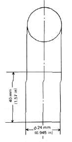
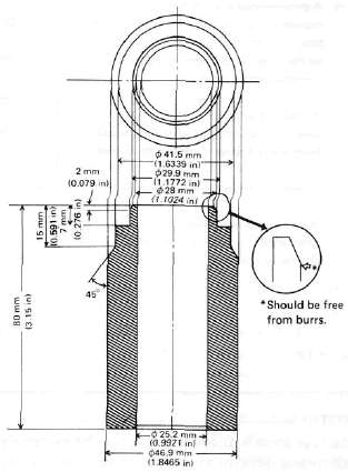
The following special tools are not available but can be constructed for the final gear disassembly and assembly:


 3. Main switch
D. Valve Spring and Lifters
1. Checking the valve springs
a. This engine uses two springs of different sizes to prevent valve float or surging. The valve spring specifications show the basic value characteristics.
CHAPTER 5. CHASSIS
A. FRONT WHEEL
1. Place the motorcycle on the center stand.
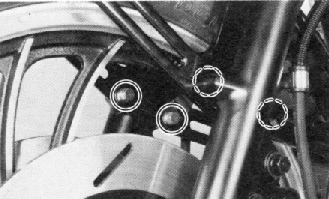
2. Remove the front fender securing bolts and remove the fender.

3. Remove the cotter pin and wheel axle nut.
F. Cylinder
1. Inspect the cylinder walls for scratches. If vertical scratches are evident, the cylinder wall should be rebored or the cylinder should be replaced.
2. Measure cylinder wall wear as shown. If wear is excessive, compression pressure will decrease. Rebore the cylinder wall and replace the piston and piston rings. Cylinder wear should be measured at three depths with a cylinder bore gauge. (See illustration.)

3. Main switch
4. Main fuse (20A)
5. Battery (12V 14AH)
19. Fuse (SIGNAL 10A}
20. Front brake switch
21. Rear brake switch
22. Neutral light (3.4W)
23. Neutral switch
24. Flasher relay
25. "TURN" switch
26. Flasher light (27VV x 4)
27. Cancelling unit
28. Horn
29. Horn switch
30. Speedometer
31. Reed switch
34. Brake/tail light (27/8VV)
1. Air valve
2. Cap bolt
3. Spring seat
4. Dust seal
5. O-ring
6. Circlip
7. Oil seal
8. Guide bushing
Front fork disassembly
Warning:
8. A.C. Generator
a. Install the rotor onto the shaft and tighten the bolt using the rotor holding tool (special tool) as shown.

1. Rotor holding tool
Tightening torque: 5.5 m-kg (39.8 ft-lb)
b. Install the stator coil assembly onto the crankcase and align the grooves on the stator core with the bolt holes on the crankcase.