FRONT FORK

1 Cap
2 Cap bolt
3 O-ring
4 Spacer
5 Spring seat
6 Fork spring
7 Damper rod
8 Inner fork tube
9 Taper spindle
10 Dust seal cover
11 Dust seal
12 Circlip
13 Fork seal
14 Washer
15 Guide bushing
16 Outer fork tube
17 Damper rod securing screw
REMOVAL AND DISASSEMBLY

WARNING:
Support the motorcycle securely so there is no damage of it falling over.
1. Loosen:
• Inner tube pinch bolt 1
• Cap bolt 2
Use Front Fork Cap Socket (YM-01104) 3

2. Remove:
• Brake caliper 1
• Front wheel 2
• Fork brace 3
3. Loosen:
• Lower front fork pinch bolts 4
CAUTION:
Support the fork before loosening the pinch bolts.

4. Remove:
• Front fork assembly (from the underbracket)
• Cap bolt 1
• Spacer 2
• Spring seat 3
• Dust seal cover 4
• Dust seal 5
• Circlip 6
5. Fill:
• Fork inner tube 7 (with fork oil)
. Stretch the inner tube before filling.
6. Install:
• Cap bolt 1

7. Remove:
• Oil seal (from outer tube).
Press the inner tube to facilitate removal.
CAUTION:
• If air enters the inner tube or it is compressed abruptly oil may spurt out or the coil seal may be ejected.
• Never touch the inner tube during a disassembly operation.
• Be sure to wrap the oil seal with a rag for safety.
Wrap with rag Spacer. Turn slowly
8. Remove:
• Oil seal
• Washer
• Cap bolt
• Fork spring
9. Drain:
• Fork

10. Remove:
• Damper rod securing bolt. Use T-handle (YM-01326) and Damper Rod Holder (YM-01365) to remove the damper rod.

11. Remove:
• Damper rod
• Damper rod spring
• Inner fork tube
• Guide bushing (from outer tube)
• Taper spindle
1 Pull inner tube from outer tube.
INSPECTION
1. Inspect:
• Inner fork tube for severe scratches, bends. Inspect for damaged oil lock valve — Replace damaged components.
WARNING:
Do not attempt to straighten a bent fork tube as this may dangerously weaken the tube.
2. Inspect:
• Outer fork tube for bends. Inspect fork seal seat for damage. Replace damaged components.

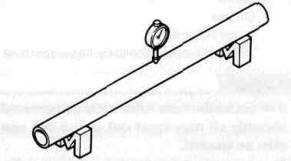
3. Inspect:
• Spring (Free length) 1
Out of specification — Replace.
Fork Spring Free Length Limit: 515 mm (20.3 in)

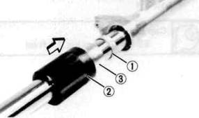
4, Inspect:
• Damper rod for worn damper rod seal 1. Replace as necessary. Check for contamination — Wash and blow out all passages.
• Slide bushing 2 for wear. Replace as necessary.
• Cap bolt 0-ring 3 for damage — Replace as necessary.
ASSEMBLY
NOTE:
Be sure all components are clean before assembly.

1 Cap
2 O-ring
3 Cap bolt
4 Spacer
5 Spring seat
6 Fork spring
7 Dust seal cover
8 Dust seal
9 Circlip
10 Fork oil seal
11 Washer
12 Guide bushing
13 Damper rod securing bolt
14 Outer fork tube
15 Taper spindle
16 Inner fork tube
17 Damper rod
18 Damper rod spring
1. Install:
• Damper rod spring
• Damper rod
Allow rod to slide slowly down the inner fork tube until it protrudes from the bottom.
• Taper spindle
• Inner fork tube

2. Install:
• Damper rod securing bolt
Hold damper rod with Damper Rod Holder (YM-01365) and T-handle(YM-01326)
Damper Rod Securing Bolt:
30 Nm (3.0 mkg, 22 ft- lb) LOCTITE® Stud N'Bearing Mount (red)
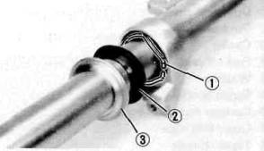
3. Install:
• Guide bushing 1
Press guide bushing into the outer fork tube with Fork Seal Driver (YM-33963) 2 and Adapter (YM-1372) 3.

4. install:
• Washer 1
• Fork oil seal (New) 2
Press fork oil seal into the outer fork tube with Fork Seal Driver (YM-33963) 3 and Adapter (YM-1372) 4.
5. Install:
• Circlip 1
• Dust seal 2
• Dust cover 3
6. Fill with fork oil.
Capacity: 383 cm3 (13.5 Imp oz, 12.95 US oz)
Type: YAMAHA Fork & Shock Oil 10WT or equivalent fork oil
7. Install (into the inner fork):
• Fork spring
• Spring seat
• Spacer
• Cap bolt
8. Install:
• Front fork assembly (into the underbracket)
9. Tighten:
• Front fork pinch bolts (Lower).
• Cap bolt
Cap Bolt: 23Nm(2.3mkg, 17ftlb)
10. Loosen:
• Lower front fork pinch bolts
11. Install:
• Front fork (into the steering crown.)
NOTE:
Be sure the inner fork tube end is flush with the top of the steering crown.

12. Tighten:
• Front fork pinch bolt (Upper) 1
• Front fork pinch bolts (Lower) 2
Upper Pinch Bolt: 20 1Mm(2.0mkg, 14 ft-lb)
Lower Pinch Bolts: 23Nm(2.3mkg, 17 ft-lb)
13. Continue assembly by reversing of Removal and Disassembly sequence. Install and torque tighten each component as specified.
Disc Brake Caliper: 35 Nm (3.5 mkg, 25 ft-lb)
Front Wheel Axle: 105 Nm (10.5 mkg, 75 ft-lb)
Wheel Axle Pinch Bolt: 20 Nm (2.0 mkg, 14 ft - lb)
- Printer-friendly version
- Log in to post comments