FRONT WHEEL
|
Basic weight: With oil and full fuel tank |
224 kg (493 lb) |
|
|
Maximum load* |
246 kg 543 lb) |
|
|
Cold tire pressure |
Front |
Rear |
|
Up to 90 kg {198 lb) load* |
177 kPa |
196 kPa |
|
90 kg {198 lb) -Maximum load* |
196 kPa |
274 kPa |
|
High speed riding |
206 kPa |
225 kPa |
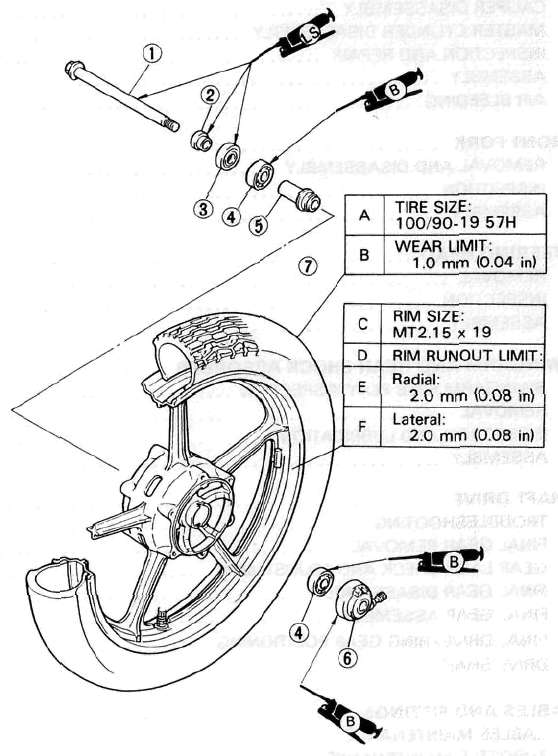
(1) Wheel axle
(2) Collar
(3) Oil seal
(4) Bearing
(5) Spacer
(6) Speedometer gear unit
(7) Tire
REMOVAL
1. Place the motorcycle on its centerstand and a garage jack under the engine.
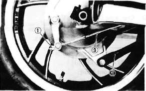
2. Remove the speedometer cable and caliper (1) from front fork
3. Loosen pinch bolt (2)
4. Remove axle (3) to release front wheel from forks

CAUTION:
Make sure the motorcycle is properly supported.
NOTE:
Do not depress the brake lever when the wheel is off the motorcycle otherwise the brake pads will be forced shut.
INSPECTION
1. Inspect: tire tread. If "Wear bars" show crosswise lines, indicatiing minimum tread depth or if there are excessive cracks the tire should be replaced.
Minimum Tire Tread Depth 1.0 mm (0.04 in)


(1) Tread depth
(2) Sidewall
(3) Wear indicator
2. Inspect the front axle by rolling the axle on a flat surface (1). Replace if bent

Warning:
Do not attempt to straighten a bent axle.
3. Inspect the front wheel for Cracks/Bends/Warpage. Replace if damaged
4. Measure wheel runout
Out of specification — Replace wheel or check bearings.

Rim Run-Out Limits:
Radial (1) : 2 mm (0.079 in) Lateral (2) : 2 mm (0.079 in)

(3) Bearing play
5. Check wheel balance.
Wheel is not statically balanced if it comes to rest at the same point after several light rotations. — Install appropriate balance weight at lightest point (on top).
NOTE:
• Balance wheel with brake disc installed.

• After mounting a tire, ride conservatively to allow proper tire to rim seating. Failure to do so may cause an accident resulting in motorcycle damage and possible operator injury.
• After a tire repair or replacement, be sure to torque tighten the valve stem locknut (1) to specification.

Valve-Stem Locknut:
1.5 Nm (0.15 m-kg, 1.1 ft-lb)
WHEEL BEARING REPLACEMENT
1. Inspect wheel bearings. If the wheel hub exhibits play or the wheel turns roughly, replace the bearings.
Wheel bearing replacement steps:
• Clean wheel hub exterior.
• Drive bearing out by pushing spacer aside and tapping around perimeter of bearing inner race. Use soft metal drift punch and hammer. The spacer (1) "floats" between bearings. Remove both bearings as described.
Eye protection is recommended when using striking tools.

• To install the wheel bearing, reverse the above sequence. Use a socket fit that matches outside diameter of bearing outer race to drive in bearing.
CAUTION:
Do not strike the center race or balls of bearing. Contact should be made only with the outer race.

INSTALLATION
1. Reverse removal procedure.
Note the following installation points:
• Lightly grease the front wheel oil seal lips and the gear teeth of the speedometer drive and driven gears.
(Use lightweight, lithium base grease.)
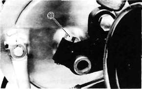
• Be sure that the two projections (1) inside the wheel hub mesh with the two slots in the speedometer clutch assembly.

• Be sure that the projecting portion (2) (torque stopper) of the speedometer housing is positioned correctly.

• Compress the front forks several times to confirm proper fork operation before tightening the pinch bolt.
Axle:
105 Nm (10.5 m-kg. 75 ft-lb)
Axle Pinch Bolt:
20 Nm (2.0 m-kg, 14 ft-lb)
Caliper:
35 Nm (3.5 m-kg, 25 ft-lb)
Rear Wheel

A. Removal
1. Place the motorcycle on the center stand.
2. Remove the tension bar and the brake rod from the brake shoe plate. The tension bar can be removed by removing the cotter pin and nut from the tension bar bolt. The brake rod can be removed by removing the adjuster.
1. Adjuster 2. Tension bar 3. Brake rod
3. Remove the axle nut cotter pin and axle nut.
4. Loosen the rear axle pinch bolt and pull out the rear axle.
1. Pinch bolt
5. Move the wheel to the right side to separate it from the final gear cases and remove the rear wheel.
E. Rear Axle Inspection
(See Front Wheel, Axle Inspection Procedure.)
F. Replacing Wheel Bearings
Rear wheel bearing replacement is similar to the procedure for the front wheel.
G. Rear Wheel Inspection
(See Front Wheel, Inspection Procedures)
H. Installing Rear Wheel
1. Lightly grease lips of rear wheel oil seals.
2. Install the wheel assembly and axle.
NOTE:
When installing the rear wheel, be sure the splines on the wheel hub fit into the final gear case. Lightly apply grease to the gear teeth.
Always use a new cotter pin on the axle nut.
Tightening torque:
Axle nut: 10.5 m-kg (75 ft-lb)
Axle pinch bolt: 2 m-kg (14 ft-lb)
- Printer-friendly version
- Log in to post comments